Hi båndsei
I understand what you mean but you must use both drawings.
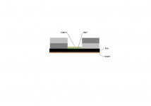
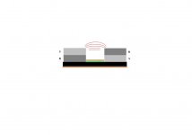
If you look to the first drawing you see clearly how the flux lines are running.
You must be in the flat horizontal flux lines with your aluminum.
Then if you look to the second drawing you know that in the first 10mm is the magnet so then begins the gap and it ends 10mm further.
This are the lower part of the graphs which is normal.
So you have to concentrate on that part of the graph.
And you see when you decrease the gap the flux gets higher in that part of the gap.
Rob
I understand what you mean but you must use both drawings.
If you look to the first drawing you see clearly how the flux lines are running.
You must be in the flat horizontal flux lines with your aluminum.
Then if you look to the second drawing you know that in the first 10mm is the magnet so then begins the gap and it ends 10mm further.
This are the lower part of the graphs which is normal.
So you have to concentrate on that part of the graph.
And you see when you decrease the gap the flux gets higher in that part of the gap.
Rob
Hi Rob.
[URL=http://img695.imageshack.us/my.php?image=billede392.jpg][IMGDEAD]http://img695.imageshack.us/img695/7532/billede392.jpg[/IMGDEAD][/URL][/IMG
On this graph the magnets are placed where the graph shows 0,and and the strong field,where the "wires" are placed goes up and down, or + and - .
As i see it, you and i see it the same way but ,"my" graph shows it better and have an accurate reading of the field strength in the place and direction the "wires".
Hope it makes sence to your.
Bernt "båndsei"
Last edited:
I suppose that only shows where the strength is
but it does not show the shape of field
Im now experimenting with copper plates, and it seems to work well
but it does not show the shape of field
Im now experimenting with copper plates, and it seems to work well

Ithink it shows the shape too. In my simm. it is shown in a distance of 2,5mm. to the magnets.
The picture abowe is with 4 magnets placed N-S-N-S.

This one shows how the field "colapses" as the distance betwine the magnets is too wide.(20mm.)
I could show a graph with one magnet.

Tinitus .It is interesting with your experiments with copper plates,it can be simmulated in FEMM. too.
Last edited:
Tinitus .It is interesting with your experiments with copper plates,it can be simmulated in FEMM. too.
Its interesting that you can simulate it, I just cant read those graphs
I built them the other day, and will post some pictures soon
btw, magnet gap is 12mm
Attachments
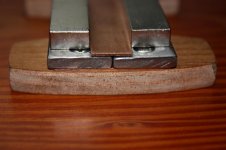
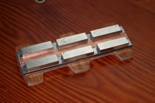
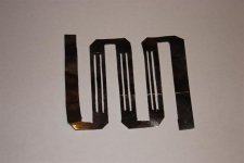
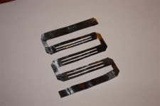
Hey, heres some shots of my magnet system
Though it is intended for a ribbon, its still the same magnet design as used in planars
Though it is intended for a ribbon, its still the same magnet design as used in planars
Attachments
Hi båndsei
I used Femm to build ribbons and don't need the positive negative graph but for your design it's maybe better because off that.
Rob
I used Femm to build ribbons and don't need the positive negative graph but for your design it's maybe better because off that.
Rob
Tinitus: Copper has no influences on the magnetic field - so what sthe point ?
Båndsei: you need to increase the number of points in your femm simulations - the field lines must be smooth. Jacked lines is because simulation brakes down.
I will try to upload picture later
Båndsei: you need to increase the number of points in your femm simulations - the field lines must be smooth. Jacked lines is because simulation brakes down.
I will try to upload picture later
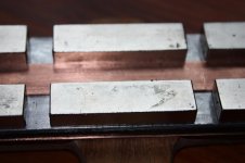
Hey, heres some shots of my magnet system
Though it is intended for a ribbon, its still the same magnet design as used in planars
How is the magnets magnetized .. thru the sides ! ....shouldn't the wide sides be for the field !!!!
Last edited:
Hi again
For Femm simulations look at;
Magnet felt oversigt
click on the links and note how smooth the field is
Båndsei - you need to increase the number of points in the femm simulation
For Femm simulations look at;
Magnet felt oversigt
click on the links and note how smooth the field is
Båndsei - you need to increase the number of points in the femm simulation
An externally hosted image should be here but it was not working when we last tested it.
An externally hosted image should be here but it was not working when we last tested it.
Last edited:
How is the magnets magnetized .. thru the sides ! ....shouldn't the wide sides be for the field !!!!
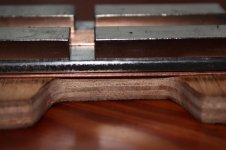
No, through the thickness
Field lines meet around the edges
And the field also strongest there, or just 1mm in front of magnets
Its easy to test with a small metal pin
You can actually feel the shape of the field
And its easy to feel when it gets weaker or stronger
The beauty of this motor design is that you can make it stronger by using similar relatively flat magnets, just wider
And field will still go from its edges
That said, it probably only work real well for ribbons, and small planar tweeters
With big planars you will experience dead zones directly in front of the magnet
Thus it makes little sense to choose wider magnets
With planars I think you need to be much more creative with the magnet/motor design
Attachments

The inherent limitations in a planer magnetic + the effort , just doesn't make any sense over a full ribbon driver, tinny ! Why not a push pull ribbon , like the Yankee ribbon, much better than doing a planer type speaker and easier to boot !
😎
😎
If you want to view some of my work, I have many pictures up of my full range planars on facebook. Here is a link to the album, if you can't see them you can add me as a friend if you wish. Soon I will set up a account on a free image hosting site to make it easier.
Here's the link Welcome to Facebook
Thanks Anthony
Here's the link Welcome to Facebook
Thanks Anthony
- Status
- Not open for further replies.
- Home
- Loudspeakers
- Planars & Exotics
- Diy planarspeakers