I knew if I let you work on it for a while you'd figure it out. The last version you show of the input selector, which has the REC OUT as the output on a separate gang/pole of the rotary, neatly does what I wanted to do but couldn't think how. You have one input selector switch PHONO-TUN-AUX-REC IN and REC IN does not connect to REC OUT. Perfect.
(Since the VSPS is external the preamp inputs are all line level. Id stick with generic labels, Source1, Source2, Source3, and REC IN.)
If money is tight, its time to seriously look at what features you need and which ones you can live without.
Me, Id do it as follows:
1. Phono preamp (VSPS) in a separate box.
2. Headphone amp (Chu moy or whatever) in a separate box. Build it later when you have the cash.
3. Passive selector switch. One box, one switch on the front, 6 switched inputs (S1-5, Rin) and three outputs (O1, O2, and Rout) where Rout is disconnected automatically when Rin is selected. Id use a 1 pole 6 position 4 gang switch and switch both the ground and signal connections. When disconnected Rout is terminated by shorting it to ground through a 1k resistor.
That's all. I'd leave all the level adjustments and VU meters to the recording software on the PC.
My 2c.
/R
sorry I just cannot understand how to do the above with 1 rotary switch and 4 leads for each switch instead of 2, with 6 sources...
I can get a standard 1x12 rotary for $3 , or a multi pole rotary for $100
so based on that, I can either utelize a cheap rotary switch and make a simple switchbox, or I might as well built a deacent pre-amp with active stages...
so this is now stevo's SS box rev 1
Unless I can do the above with being able to switch the grounds - ie keep audio isolated, thats probably what I'll do for the moment.
Will linking all the grounds together be a problem?
hahaha each revision I do, gets less and less bits in it...
I am guessing also this is a break before make switcher...
& I already have a wall powered cmoy which I am using at the moment, which is why I wanted to make the switcher, so I don't have to switch between amp/headphones by crawling into the back of the computer, and also so I don't have to change source if I want to listen to something else, ie radio.
edit - just found an 8 pole 5 position rotary for $14aud or about $10us ea... is that fair?
I can get a standard 1x12 rotary for $3 , or a multi pole rotary for $100
so based on that, I can either utelize a cheap rotary switch and make a simple switchbox, or I might as well built a deacent pre-amp with active stages...
so this is now stevo's SS box rev 1
An externally hosted image should be here but it was not working when we last tested it.
Unless I can do the above with being able to switch the grounds - ie keep audio isolated, thats probably what I'll do for the moment.
Will linking all the grounds together be a problem?
hahaha each revision I do, gets less and less bits in it...
I am guessing also this is a break before make switcher...
& I already have a wall powered cmoy which I am using at the moment, which is why I wanted to make the switcher, so I don't have to switch between amp/headphones by crawling into the back of the computer, and also so I don't have to change source if I want to listen to something else, ie radio.
edit - just found an 8 pole 5 position rotary for $14aud or about $10us ea... is that fair?
Okok... I was forgetting stereo has two channels.. 🙂
If three inputs are enough, use the 3 position 4 pole switch. Forget what I said about switching the ground lines. Just switch the signals as you have drawn. Looks like you're good to go.
/R
If three inputs are enough, use the 3 position 4 pole switch. Forget what I said about switching the ground lines. Just switch the signals as you have drawn. Looks like you're good to go.
/R
haha yea, anyway made it easier to read in rotary type style.
If I get ground loop hum problems, I guess I'll have to get a 8 pole ~3 way rotary.
hahaha damn I'm a tightarse sometimes 🙂
thanks for you guys helping me out.
I'm still awaiting some Soha/stoopid pcb's 🙂, and I'll be building a GainClone clone? at some point to hehehe 🙂
If I get ground loop hum problems, I guess I'll have to get a 8 pole ~3 way rotary.
hahaha damn I'm a tightarse sometimes 🙂
An externally hosted image should be here but it was not working when we last tested it.
thanks for you guys helping me out.
I'm still awaiting some Soha/stoopid pcb's 🙂, and I'll be building a GainClone clone? at some point to hehehe 🙂
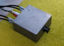
worked perfectly thanks RJM.
got a little cast aluminium case that can fit switch & RCA's out the back & will just fit a headphone amp ( yet to do, as I have enough bits lying around to do this some time in the next few weeks), in the mean time I'll use the external headphone amp & switching is perfect.
now I just got to fix up my digital tv recording box - keeps BSOD-ing...
Here's mine. 3 position 4 pole switch. I have three inputs but only a single output and I switch the input grounds as well as the signal wires. With 20/20 hindsight I would have probably added a second output to use with my headphone amp, as you have. Oh well. The case I picked is too small for a retrofit. /R
Attachments
Power supply
Okay - been searching for a project for a while now, and since my trusty Carver preamp has finally kicked off, I am left in need of a phono preamp for my B&O.
Thing is, until now, I've only built battery-powered headphone amps. I never built a true power supply using 120V before.
After doing a lot of reading, I think I understand the basics, but I do not understand the diagram supplied on RJM's website. Any chance I could get a moron's guide to putting together the power supply portion of this phono preamp, starting from the wall outlet and ending at the V+/V- nodes in the circuit diagram?
As unconventional as it sounds I suggest you bypass Google and make a trip instead to your local library. You'll find all you need to know in any introductory electronics text. /R
Gotcha. Well based on what I read herehere I now understand your power diagram.
I suppose now I'm just searching for part recommendations.
1) Any preference on the transformer for achieving the +/-17V shown? I'm considering the following from DigiKey:
MT7277-ND
MT7279-ND
MR7280-ND
PC-24-35-ND
2) I'm unclear on lingo - "full wave rectifier" (from your most excellent guide) means a four-diode bridge rectifier, correct? Any suggestions?
3) What value(s) on the fuse?
4) COM in the power diagram connects to GND in the circuit diagram, yes?
5) Is the smoothing done by the four capacitors in the regulation circuit?
I'm trying to use Digikey or Mouser exclusively, if possible.
1. Get the Talema T62082 50 VA 2x12 V. $18.83 at Digikey.
2. Use two GBPC2501/1GI-ND 100V 25A bridge rectifiers. $5.51 each. For example only. Anything over 1A will be fine but these big guys have a center hole and thus are convenient to mount to the chassis.
3. Try 0.25A slow (On a 120V line.)
4. Yes. My bad.
5. Technically only by the first two, on the input to the regulator. The other two on the output are for filtering and bypassing.
Hmmm - that transformer doesn't show up in the DigiKey search results - do they still carry it?
I know its not the same, but my VSPS is running off a 2VA x 2 x 12V PCB mount transformer... used a 1.5VA before but that got a bit warm after long use...The opamps can normaly only put out about 40mA per channel, so I saw no point in giving it 10 times the power needed. Oh and it sounds wicked.... and I used to run it off a giant 12V tranny for the year before that, so I could do a fair comparison.
Digikey Part TE62082-ND. Sorry, the "E" got dropped in the previous post. Silly keyboard, no cookie. Search for 62082 and it'll come up.
Of course any 2x12V transformer will work. I've made that clear before. However, Wylock asked for a direct recommendation and the above is what I'd buy for the application, given its high quality and power / price ratio. Ditto with the diodes - anything goes.
Of course any 2x12V transformer will work. I've made that clear before. However, Wylock asked for a direct recommendation and the above is what I'd buy for the application, given its high quality and power / price ratio. Ditto with the diodes - anything goes.
I just finisched a VSPS-ultra and tried it on a Benz gold with 4mV output. I hear a hum (tried a rectangular transformer) but the music is distorted also. Putted it on a line-level tube headphone amp to try.
I have to check everything, but i think it is done right.
Sound is distorted in low level, it seems there has to be some voltage before the whole starts to amplify.
I have to check everything, but i think it is done right.
Sound is distorted in low level, it seems there has to be some voltage before the whole starts to amplify.
I noticed that the schematic showed the resistor + cap of the RIAA where the resistor is on the (-) side and the cap connects to the output.
The layout had it in reverse.
So which one is correct?
The layout had it in reverse.
So which one is correct?
arnoldc said:I noticed that the schematic showed the resistor + cap of the RIAA where the resistor is on the (-) side and the cap connects to the output.
The layout had it in reverse.
So which one is correct?
I don't think this is a problem, it forms two zobels.
I have checked everything yesterday, and do not understand why my VSPS ultra is distorting. A toroid PS reduced the hum though.
"A toroid PS reduced the hum though."
Well, that at least indicates part of the problem: either the vsps is not shielded properly or you've connected the grounds incorrectly.
I guess the latter, that the return currents to the power supply are being coupled into the input section of the circuit via a "ground loop".
/R
Well, that at least indicates part of the problem: either the vsps is not shielded properly or you've connected the grounds incorrectly.
I guess the latter, that the return currents to the power supply are being coupled into the input section of the circuit via a "ground loop".
/R
rjm said:"A toroid PS reduced the hum though."
Well, that at least indicates part of the problem: either the vsps is not shielded properly or you've connected the grounds incorrectly.
I guess the latter, that the return currents to the power supply are being coupled into the input section of the circuit via a "ground loop".
/R
Yes the toroid helped, but still the sound is very distorted. Each channel equal, so it must be something in the schematic. The value's of feedback caps/resistors from pin 2 to 6 are correct. +/-12V regulted PS to pin 7/4 also, pin 3 Gnd. I used LT1115.
- Status
- Not open for further replies.
- Home
- Source & Line
- Analogue Source
- DIY phono preamp - cheap and simple!