Well at that point the send is unbalanced and the hi-z inputs are as well. I think they both have sufficient gain and low enough noise floors that it may actually work. Now how flat and flexible I can make that RIAA circuit I dunno.
I guess I want a tweakable RIAA box to compensate in variations of the inverse RIAA used. Easier to think of than impliment.
I guess I want a tweakable RIAA box to compensate in variations of the inverse RIAA used. Easier to think of than impliment.
Yesterday I built the first VSPS. I am impressed. I used Vishay Resistors and two very good 4,7 µF Caps.
My problem: the right Channel does funktion, the left one not. I think that a 1nF - Cap is not okay because the RIAA filtering seams not working.
For the PSU I used 8 diodes like the PSU from the gainclone with an 12 v Toroid and 7912 and 7812 for Voltageregulation.
I built it point to point on a vero-board. The wires are Mundorf silver-gold.
Sorry for my bad English.
It's unlikely the capacitor was bad, unless you melted it while soldering it in place.
More likely you have a bad solder connection, or connected the components incorrectly, or mixed up the resistor values.
Showing us photos of your work helps with troubleshooting.
More likely you have a bad solder connection, or connected the components incorrectly, or mixed up the resistor values.
Showing us photos of your work helps with troubleshooting.
ok, I'll look. One C is maybe damaged. The values of the resistors I have to check. Thank you for your help.🙂
I found the failure. I made a second Phonopreamp. The problem was the same. So, i thoght, the last thing can be a cable. That was not the problem, too.
The problem is my little gainclone. I lent it to a freind and he decided not to say, tha ther is a problem on the left channnel.
Now I've got to vsps.
Another question: The revisions wich are made on the RIAA shown at post #1041 - is it good and should I do this?
The problem is my little gainclone. I lent it to a freind and he decided not to say, tha ther is a problem on the left channnel.
Now I've got to vsps.
Another question: The revisions wich are made on the RIAA shown at post #1041 - is it good and should I do this?
Unless someone has put one together when I wasn't looking, the answer is no.
The closest I can think of is the construction guide.
Perhaps someone building one of the Sky Coral kits would volunteer to keep a photo diary during their building of it?
The closest I can think of is the construction guide.
Perhaps someone building one of the Sky Coral kits would volunteer to keep a photo diary during their building of it?
I'm building myself the VSPS, however I have a question about the power input.
Instead of the 3 pin XLR power jack, can I just a 2.1mm DC power jack instead?
I'm building my PSU based on this:
http://www.rock-grotto.co.uk/easyxpsu.htm
and the output of that PS uses 2.1mm power cables.
Is that okay? Is the PS type suitable for the VSPS?
p.s. My knowledge on electronics only extends up to holding a soldering iron....
remeron said:p.s. My knowledge on electronics only extends up to holding a soldering iron....
Indeed, and the website you are following is at the same level, without even a circuit diagram to help you know if it's right for you or not.
Unfortunately it's not, since the supply shown is a single supply rather than a split supply, with only two output wires not three.
For the VSPS you need a transformer with two output windings, and a connecter with at least three pins. It doesn't have to be an XLR of course, but that's the most common.
Oh crap....
I've just bought the transformer toroidal, which is this one:
http://malaysia.rs-online.com/web/s...chProducts&searchTerm=223-8538&x=0&y=0#header
is this part that i bought at least correct, or did i just waste my money?
Are there any adjustments that can be made to the PS so that it provides 3 output?
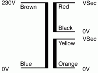
Lemme see if i got this right.....below is the schematics of the toroidal that i bought:
Basically, since the VSPS needs a 12-0-12 rails...
Everything on the PS website (http://www.rock-grotto.co.uk/easyxpsu.htm) applies EXCEPT the out put part from the toroidal.
So instead of 2 outputs like the ones on the site, I need to do a 3 output.
Which means the red, yellow and combined black+orange and this would give me a 12-0-12 rail output. Is that right?
Attachments
i'm getting a newbie epiphany here 🙂
I guess my previous post is somewhat naive..
Correct if i'm wrong...
As i was saying previously...the layout is the same as the website i mentioned, however the out from the toroidal needs to be connected to a rectifying diode and that would give me a 12-0-12 railing
(as per diagram on the VSPS page).
am i correct?
rjm said:Relax, that transformer will be perfect.
Thanks... 🙂
Anyway...could you help me out about the toroidal output?
So far I gather,
the Black + Orange combined to give me 0
The Red and Yellow would go into a ?bridge rectifier diode.
Is that ok?
thanks rjm.
as i have a spare nad pp2 lying around, i was thinking of using the power supply to hook that pp2 as well.
the pp2 runs on 24vdc...with the setup like the one on the website, will that run my pp2?
as i have a spare nad pp2 lying around, i was thinking of using the power supply to hook that pp2 as well.
the pp2 runs on 24vdc...with the setup like the one on the website, will that run my pp2?
Yes, connect the COM to the rectifier (-) output instead, and add an LM7824 in there somewhere...
i finally got all the parts for the vsps and my power supply 😀
got everything figured out with the advise from very helpful people 😉
was fixing and soldering when i suddenly didn't know what to do with my switch on my power supply!!! Aiieee
I bought myself a Illimuniated dpst switch and it has 6 solder points behind.. i was just expecting 4...
they are labelled
1 4
2 5
3 6
i know that i need to connect 1,4 to my transformer and 2,5 to my power. but what's 3,6? i take it it's for my LED in the switch. how do i connect those?
I think you do not need 3 and 6, just forget about them. In addition, I think you do not need 4 and 5, you can use just 1 and 2 for power switch on/off.
Northernsky
Northernsky
- Status
- Not open for further replies.
- Home
- Source & Line
- Analogue Source
- DIY phono preamp - cheap and simple!