Hello mr. rjm
I have finally decided to tell you that I'm also a happy guy building one of your phono amps. The simplest of them all. The VSPS with one OPA2134 for both channels. I did want to have something better then the one I used but not to much because my MarkII reference will be my long time aftersought tubestage. And a design of my own. Even though that one will be very colored by John Broskies infants at Tubecad. 😉
Today I also tested my new loadplug's. I have done a pair of 47k plugs as the load for the cartridge. I maybe will do some trim but today I saw (heard) the light so it will maybe take some time. 🙂
I tested a new cheap but allaround good cartridge today. An Audio Technica AT95E. Wow ! My old Pickering XSV3000 from the late 20's century had to go to rest. Now I have to listen to all my collections of vinyl again.
I have built an LCR meter kit from a genius in France that I have measured my cartridges with.
This new MM pickup measures 420mH and 3k ohm Z at 1khz. The specs say 2.8kohm and 400mH so they are near what they advertise. 🙂
I load it (with my plugs) to 45k ohm and 150pF. Cables from turntable gives 120Pf and input to OP amp is 30pF.
AT recommend a capacitive load of 100 - 200pF so I should do fine. And the result. I'm very pleased. It was OK before but with this new cartridge, even though it was cheap, is awesome 😀
Thanks for the PCB layout in Eagle rjm.
Final Version of VSPS.
I did the change at RIAA. It means: Change R6 and C3, cut the end of R3 and R4, soldered it between C3 and R6. Second I put 100 pF and 470 µF between power-legs from the OPA. Third I decrease R2 to 580 Ohm to increase the gain a little bit. The last thing: I changed R1 from 47 kOhm to 100 kOhm and there is now a carbon-resistor. The sound is very, very good and the R1 in carbon-version gives a natural sound. Before I used a vishay-Dale 47 kOhm.
In the PSU there are working LM 317 and 337. That is very important.
Thanks to RJM and all the other DIY-Members for hints and helps.
The next thing in future would be the Phonoclone.🙂
VSPS and Gainclone are working together in perfect mode for a perfect sound.
Good link about loading the cartridge
Cartridge loading @ Vinylengine
The simulation software:
Beige Bag
Cartridge loading @ Vinylengine
The simulation software:
Beige Bag
Hello..
I need some help.
Currently I'm trying to set up a turntable for my dad and I'm using the VSPS (with 40db gain) with a Rega P3-24 with Denon DL-160 cartridge.
His sistem is currently an old Lumley Reference pre-amp which is hooked up to a Threshold power amp. I got everything set up but eh sound coming is reallllyyyyy soft. At max volume, the is just audible.
What am i doing wrong? is there something missing?
If you are sure there is music coming from the speakers, not just the stylus, then the most likely scenario is the VSPS was connected to line1 input but you have the preamp set to phono, or some other mismatched combination of connection and selections.
And old preamp should have a phono stage built in, so you can check first if that works before switching to the outboard VSPS.
And old preamp should have a phono stage built in, so you can check first if that works before switching to the outboard VSPS.
I finally complete building a VSPS.
I got dipswitches to change
input resistance: 10R,100R,1K,47K
input capacitance: 0, 10pf,47pf,100pf,220pf
(can be paralell as well)
Gain. 40db and..maybe 60db not decided yet.
And switches to "turn on/off" dcblocking caps (4,7mf bipolar)on the output.
With input shorted I got som humming issues, signal groundloop somewhere. With he inpt open I got "100db" humming.
Must fix a picture so maybee someone can find it.
I use the LM4562 as opamp.
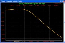
Some measurement. With no dcblocking caps.
Channel1. 50 mV
Channel2. 230mV
best regards..
I got dipswitches to change
input resistance: 10R,100R,1K,47K
input capacitance: 0, 10pf,47pf,100pf,220pf
(can be paralell as well)
Gain. 40db and..maybe 60db not decided yet.
And switches to "turn on/off" dcblocking caps (4,7mf bipolar)on the output.
With input shorted I got som humming issues, signal groundloop somewhere. With he inpt open I got "100db" humming.
Must fix a picture so maybee someone can find it.
I use the LM4562 as opamp.
Some measurement. With no dcblocking caps.
Channel1. 50 mV
Channel2. 230mV
best regards..
VSPS 300
It's been on my mind for some time to transfuse some of the Phonoclone 3 goodness back into the VSPS circuit. Some of you may not have noticed, but the Phonoclone and VSPS share a lot of DNA. Because most people building the VSPS are looking for cheap and simple the "advanced" phonoclone has received all the latest and greatest doodads all the while the VSPS commonly mostly saw action as the "dumbed down" stereo board.
Not any more:
What you are looking at is the Xreg voltage regulator from the phonoclone 3 attached to a single channel VSPS. Double-sided board, ground plane, dual mono design, and anytime upgradeable to the Phonoclone 3 should you wish to go MC as the boards share the same mounting holes. Additional benefit over the Phonoclone is the extra 2" wide set of though-holes for C3.
I'll post the .brd files in a couple of days. Still a preview version at present.
I want to double check what size of capacitor is typical for C0 (cartridge load) and C1,2 if film caps (vs. mica) are to be used.
/rjm
It's been on my mind for some time to transfuse some of the Phonoclone 3 goodness back into the VSPS circuit. Some of you may not have noticed, but the Phonoclone and VSPS share a lot of DNA. Because most people building the VSPS are looking for cheap and simple the "advanced" phonoclone has received all the latest and greatest doodads all the while the VSPS commonly mostly saw action as the "dumbed down" stereo board.
Not any more:
An externally hosted image should be here but it was not working when we last tested it.
What you are looking at is the Xreg voltage regulator from the phonoclone 3 attached to a single channel VSPS. Double-sided board, ground plane, dual mono design, and anytime upgradeable to the Phonoclone 3 should you wish to go MC as the boards share the same mounting holes. Additional benefit over the Phonoclone is the extra 2" wide set of though-holes for C3.
I'll post the .brd files in a couple of days. Still a preview version at present.
I want to double check what size of capacitor is typical for C0 (cartridge load) and C1,2 if film caps (vs. mica) are to be used.
/rjm
Fantastic
Hi rjm
You are very friendly to share your artwork in Eagle, which I guess have taken a lot of time to finish. I know, I use it myself.
I want to build a tubed phono stage before I die , but this VSPS 300 would have been great to have
  as a compare kit between the tubed stage and the very simple, one IC phonostage, which for the moment is my reference phono stage. Se my comments above.
Awesome 🙂
Hi rjm
You are very friendly to share your artwork in Eagle, which I guess have taken a lot of time to finish. I know, I use it myself.
I want to build a tubed phono stage before I die
, but this VSPS 300 would have been great to have as a compare kit between the tubed stage and the very simple, one IC phonostage, which for the moment is my reference phono stage. Se my comments above.Awesome 🙂
That's great idea to insert regulators on preamp board Richard. I do this for a few years and allways recommend.
Also I recommend thin signal traces, not so wide.
Caps C1 C2 you may turn left 90 degrees - shortest signal path.
Close to the power pins you may add place for 100nF and 1-4,7uF tantal - thats too very audible.
Interesting: VSPS vs Primare R20
two weeks ago we compared VSPS with Primare R20 ( about 700$ ). Won VSPS in 30 seconds 🙂.
And it wasn't dual mono but our polish forum version on dual opamps (NE5532 !). More air, deeper bas, deeper soundstage. Very good vocals.
Regards K
ahaja said:That's great idea to insert regulators on preamp board Richard. I do this for a few years and allways recommend.
In fairness they've always been on the board. I've just replaced the LM7812 or LM317 etc. with something a little more interesting.
Also I recommend thin signal traces, not so wide.
Caps C1 C2 you may turn left 90 degrees - shortest signal path.
Close to the power pins you may add place for 100nF and 1-4,7uF tantal - thats too very audible.
Advice noted. Thanks!
Richard
(I don't share your opinion on 100nF film bypass caps - well I agree they are audible, just not in a good way - but you can add them if you like either on the pins directly or at C14,15 using C16,17 for the electrolytic.)
VSPS revision 45c
I have tentatively revised the standard VSPS layout as follows:
Single-sided PCB, same dimensions as before.
Summary of changes:
- moved the output to the right side of the board, so I could then tuck the bypass caps C6,C7 right next to the ICs power pins and still maintain the correct grounding order.
- widened the pads of C3 to 2" apart, so a large film coupling cap can be more easily accommodated.
- input power pins now labeled V++ V-- (a convention I am trying to roll out over all the boards now, to mean unregulated, unfiltrered, rectified DC input voltage ... )
Eagle files attached.
@2A3SET : no, the VSPS RIAA network has an extra resistor which alters the values fractionally.
/rjm
I have tentatively revised the standard VSPS layout as follows:
An externally hosted image should be here but it was not working when we last tested it.
Single-sided PCB, same dimensions as before.
Summary of changes:
- moved the output to the right side of the board, so I could then tuck the bypass caps C6,C7 right next to the ICs power pins and still maintain the correct grounding order.
- widened the pads of C3 to 2" apart, so a large film coupling cap can be more easily accommodated.
- input power pins now labeled V++ V-- (a convention I am trying to roll out over all the boards now, to mean unregulated, unfiltrered, rectified DC input voltage ... )
Eagle files attached.
@2A3SET : no, the VSPS RIAA network has an extra resistor which alters the values fractionally.
/rjm
Attachments
I am building a VSPS. Thanks very much for the design!
I am putting the power supply and the amp circuit into the same box against your recommendations (for convenience' sake).
The case is a tea tin (metalic). I have connected the AC ground to the case. I am planning to keep the amp circuit safe from interference in another smaller tin inside the case which is sonnected to the DC common ground. I was planning to keep this isolated from the bigger case.
Does this seem smart to you?
Where do I connect the phono ground from the turntable (easiest would be to connect it to the big case which is AC grounded)?
Guide
Humor me by adopting my conventions for the terminology here:
AC ground : EARTH
Circuit ground: COM
Case: GND [a bolt on the back of the case]
COM, GND, and the turntable ground *must* connect to each other. The connection to earth is *optional* and will likely have to be left out to prevent ground loops... to repeat: connecting AC ground to the case is likely to cause hum.
Turntable ground connects to GND. Circuit common also connects to GND, usually at the same bolt, with a lug fixed from the inside.
The question is, for a stereo VSPS, at what section of the circuit common, COM, do you make the connection to GND? COM runs all the way from the inputs, IN-, to the power supply recitifers.
Two options come to mind:
1. run a wire from the COM pad on the circuit board to GND, connect the COM wire from the rectifiers to the same GND. This is how it has to be done with dual mono boards and a single power supply.
2. Run the COM wire from the rectifiers directly to the COM pad on the board, and run wires from the input RCA outer shell (or IN-) to GND. This option is available to the stereo VSPS and dual mono boards with separate power supplies.
Option 2 is probably the best bet if you insist on having an earthed, shared chassis.
-Richard
The RJM Audio website has moved. You can find the Phonoclone and VSPS pages at the URLs shown below:
Phonoclone phono stage
phonoclone.com/diy_pho4.html
VSPS phono stage
phonoclone.com/diy_pho5.html
Printed Circuit Boards for VSPS and Phonoclone
phonoclone.com/diy_pcb.html
Contruction Guide for VSPS and Phonoclone
phonoclone.com/diy_guide.html
Phonoclone phono stage
phonoclone.com/diy_pho4.html
VSPS phono stage
phonoclone.com/diy_pho5.html
Printed Circuit Boards for VSPS and Phonoclone
phonoclone.com/diy_pcb.html
Contruction Guide for VSPS and Phonoclone
phonoclone.com/diy_guide.html
how about R4 with 31.6K
Hi RJM,
Should I use 31.6K instead of 33K for R4 for better accuracy (by chance have a pair of C1 and C2 with 0.5% acuracy). I did calculation based on 732K/105K for R5/R4 in new VSPS.
If I just need 30db, should I use R2 680ohm and R3 220ohm instead?
LowZ Values
R2 220 ohms
R3 680 ohms
R4 33k ohms
R5 220k ohms
C1 3.3nF
C2 10nF
I can tell you've done your homework.
I ran the simulation with the values you listed. 33k gives 0.25 dB accuracy, 31.6k is essentially perfect.
So yes, it's worth trying to find / combine resistors to drop from 33k to 31.6k.
How about 33k and 750k in parallel? That would do the trick...
Richard
I ran the simulation with the values you listed. 33k gives 0.25 dB accuracy, 31.6k is essentially perfect.
So yes, it's worth trying to find / combine resistors to drop from 33k to 31.6k.
How about 33k and 750k in parallel? That would do the trick...
Richard
- Status
- Not open for further replies.
- Home
- Source & Line
- Analogue Source
- DIY phono preamp - cheap and simple!