Summing up:
It is true that I penalized the 3-gapper by adding extra gap spacing, but it was a matter of necessity to flatten the BL curve. Keeping an eye to simplicity and expense, we could certainly explore other 3-gap architectures that might manifest less BL variation.
The nice thing about the DDD topology is that it turned those stair-stepped BL curves against each other and netted an extremely well-behaved plot. (It looked so good, I checked myself a couple times to be sure it wasn't a fluke!)
This tells me that the DDD topology is suited to my inexpensive nested square tubing approach, where the Tri-gapper may not perform to its full potential. At the very least, it tells me that the DDD approach should not be entirely discounted, as it seems to perform equally or better than the tri-gap in this situation at equal minimum clearances. And I'm convinced the DDD will always return a significantly lower Le.
Dan earlier pointed out that deeper motors generally need more clearance. I can see how this is especially true with topologies (like the tri-gap) where the VC is supported on a single end and cantilevered into the gap(s). In that case, any radial deflection of the spider is proportionally magnified by the cantilever.
However, when you support the VC former on both sides of the motor, radial VC movement is limited to no more than that of the spider(s).
I'm not saying we necessarily should do this thing one way or the other. I'm not personally sold on one over the other just yet--I just wanted to point out that it's a closer race than some may think.
Just my hundred and two cents, folks...😀
Very informative Bill, goood work! I'm also attached to the elegance of the 6 gap approach.
A quick question about the whole sqaure tubing approach: How do you account for that fact that the design is non uniform when cosidering the 3rd dimension. i.e. the FEMM plots are a 2D slice which in convention motors you expect to spin round [lathe]. So each point in the gap around the perimiter of the pole can be accepted as the same. However, I see a potential bottleneck as this design wlil no be spun round as such. This applies to the multi-magnet-in-the-base approach as well (Perthenon, Audiom). Perhaps Focal and Adire use a 3D FEA program?
A quick question about the whole sqaure tubing approach: How do you account for that fact that the design is non uniform when cosidering the 3rd dimension. i.e. the FEMM plots are a 2D slice which in convention motors you expect to spin round [lathe]. So each point in the gap around the perimiter of the pole can be accepted as the same. However, I see a potential bottleneck as this design wlil no be spun round as such. This applies to the multi-magnet-in-the-base approach as well (Perthenon, Audiom). Perhaps Focal and Adire use a 3D FEA program?
Vikash,
I'm not really a FEMM guru, so I don't know if you can set up an exact model with a cylindrical pole piercing three sections of square tubing in FEMM.
I defined the above models as axisymetric, so in a section of square tubing, the flux distribution would be different from the gap outward radially. But I believe it should be quite similar from the gap's outer boundary inward.
When it comes time to build, just remember to spec square sections that are longer than half the circumference of the gap. That way, the flux bottleneck should occur at the gap (or the pole/magnet boundary, as seems to be the case with my models).
I agree with you about the reduced rocking with mirrored spiders and a long VC former. Without the typical cantilever action, there shouldn't be any problem. In fact, and this is just the hunch of an engineer experienced with mechanism design, I'd say that it is very likely that the six gap DDD extended voice coil design would exhibit less rocking for just that reason, allowing reduced gap clearances. The further the spacing of the two spiders, the better control over VC rocking, and the lower the required clearance. The mirrored DDD topology seems to promote that characteristic.
Other observations from the above FEMM plots... and this has been something that has been nagging me in this thread. OK, I asked the question earlier about what a "linear" suspension really means. We all seemed to agree that it meant suspension force increases linearly with excursion, instead of non-linearly. We also seemed to agree that ideally you would want a uniform suspension force that wasn't excursion dependent.
Here's my thinking... correct me when it gets crazy. 🙂 Signal voltage levels represent the amplitude of a given sine wave. That sine wave represents the volume of the recorded sound. Microphones are fairly linear, so if sound A causes 2X the microphone diaphram excursion of sound B, it should be fairly accurately transferred as 2X the recorded waveform amplitude of B, and after playback from a given source signal A should have 2X the maximum voltage level as signal B. Right?
Now when that amplified signal is played by a driver, the hopes are that the driver would reach 2X the excursion driven by A than by B, which accurately mimics the conditions present at the recording microphone. However, with a flat BL curve and a linearly progressing suspension force, 2X the drive voltage will produce somewhere significantly less than 2X the excursion. I'm sure this accounts for some form of compression that is often mentioned. Perhaps power compression?
Right... now in the real world, you can't easily make a constant force suspension, but can you offset a linear suspension with a linear BL curve? Looking at Bill's graphs above, I get the feeling that a multigap motor of some suitable configuration (don't you just love those completely uninformative and ambiguous definitions? 🙂 ) could produce a BL curve that was weak in the middle (where suspension force is low) and stronger at higher excursions (where suspension force is higher). Perhaps you would always be left with a step? Perhaps you could get a nice "V" shape? Perhaps you could offset power compression to some degree?
Just a thought. I have weird thoughts. It's Monday, and I didn't get much sleep last night 🙂. I need coffee and sugar, but I'm still left wondering how bad the drawbacks are to offsetting one linear force with anouther linear force to produce a motor that really is linear?
Peter J,
I entirely agree that this may be an excellent application for linear motors (or for rotary motors with rotary-to-linear conversion).
The moment I get a sniff of such a system that's simple to build, cheap, and quiet, I'll jump on the bandwagon!
HR,
Your wierd little caffeine/sucrose/sleep- deprived thought deserves a good answer. Like you, I have my theories, but I'm worried they may be incomplete on the physics end of things. I'd love to hear an authoratative answer. Dan? Anyone?
Shouldn't there be a break-even point, when Xmax is so large, that a linear motor design would make more sense then the traditional voice coil?
I entirely agree that this may be an excellent application for linear motors (or for rotary motors with rotary-to-linear conversion).
The moment I get a sniff of such a system that's simple to build, cheap, and quiet, I'll jump on the bandwagon!
HR,
Your wierd little caffeine/sucrose/sleep- deprived thought deserves a good answer. Like you, I have my theories, but I'm worried they may be incomplete on the physics end of things.
I'd love to hear an authoratative answer. Dan? Anyone?I have a pretty good grasp of physics. Really strong on mechanical systems and mechanisms, but still a decent understanding of electromagnetics and electronics. Never tried to apply any of that to driver design though, so many of the questions I ask are probably speaker design 101 type questions... valid questions I think, but probably answered a few decades ago. 🙂
BTW, I downloaded FEMM. Pretty neat program, except I have no idea how to use it and haven't had a chance yet to read through any manual. Looks like importing geometry from ACAD through .dxf works pretty well, so I won't have to fret with creating geometry in FEMM. The material library has 1018 and N40, though I can't figure out how to apply those materials to the different regions of geometry. Oh well... when I get more time this looks like it will be fun to play with.
Question for you magnetics guys... assuming a fixed number of gaps and gap widths, and fixed magnetic return path (thickness, steel grade, etc.), is the primary flux limitation the volume of NeFeB in the circuit or the cross sectional area of NeFeB through the magnetic circuit? I have some ideas of how to increase the amount of magnet in the return path pretty easily, but I need to know which is more important.
Question for you magnetics guys... assuming a fixed number of gaps and gap widths, and fixed magnetic return path (thickness, steel grade, etc.), is the primary flux limitation the volume of NeFeB in the circuit or the cross sectional area of NeFeB through the magnetic circuit? I have some ideas of how to increase the amount of magnet in the return path pretty easily, but I need to know which is more important.
Cross-sectional area is the primary factor (assuming magnets with flat poles, the area of the pole surfaces). Stacking magnets, it takes something like a stack of ten to double the flux of a single magnet.
To get a running start with FEMM, take a look at the example problems on the website.
To get a running start with FEMM, take a look at the example problems on the website.
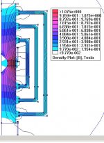
Cross-sectional area... good. The following image shows a 2" x 2" x .25" N40 magnet in the return path. This would require some welding, but the primary return path structure is still comprised of standard box sections. They are simply ripped in half, and welded to two plates that sandwich a line of these 2x2x.25 magnets. Lots of extra surface area... magnets are less than $15 each, so relative to the rest of the project cost not bad.
The reason the first two gaps share a return is because to provide room for a 4.25" ring magnet in the pole + adequate gap width required the central section to be rectangular and turned 90 degrees to the other to avoid interference. However, with an axisymmetric FEA I figured you could just model a common return path for a first rough cut.
The section sizes I used were 8x6, 10x8, and 14x10.
Attachments

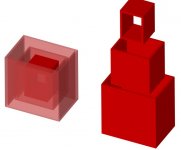
To get a better idea of how the three box sections are arranged, here is a rendered image showing them assembled and disassembled. This doesn't show the hole for gaps, nor does it show the central plate gap for additional magnet area. I'll have to add that tomorrow.
Now that I think about it, magnets in the return path are really only a form of stacking magnets, except that in this configuration you could get much more surface area than a magnet inside the former/pole piece. Which makes you wonder if it would be more cost effective to abandone the pole piece magnet altogether ($100) and only use magnets external. Not nearly as nifty looking, but perhaps more practical. 🙁 🙂
Now that I think about it, magnets in the return path are really only a form of stacking magnets, except that in this configuration you could get much more surface area than a magnet inside the former/pole piece. Which makes you wonder if it would be more cost effective to abandone the pole piece magnet altogether ($100) and only use magnets external. Not nearly as nifty looking, but perhaps more practical. 🙁 🙂
Attachments
RHosch, based on the same conclusion, I've been working on a similar idea. These magnets are only 0.5". These could be applied to both the square tubing, or rods (sneaky sneaky) like in the Parthenon. I can't see it being difficult to get 0.5" thick rods. Add a thick steel base and top plates and voila! I'll have a look at the cost of small mags, but anyone think using steel rods and cutting large round steel plates with centre holes is much less feasible than cutting holes in square tubing?
Attachments
Bingo! 😎Bill F. said:Peter J,
I entirely agree that this may be an excellent application for linear motors (or for rotary motors with rotary-to-linear conversion).
I honestly don't know much about the inner mechanics of these linear motors, but I can't imagine for the life of me that they would be suitible, or you'd see them in application somewhere.
In fact, is anyone here equipped with enough information on them to be able to make that call? Can anyone answer why they aren't in application in this sort of capacity?
On the other hand, a rotary servo motor has many benefits that would prove valuable here:
It's got an inherently ruler-flat BL curve. It's not a curve. It's literally a BL line. That's cool. 😉
It's got a very high efficiency... motor force generated per watt of input.
A traditional subwoofer is typically between 0.5% and 1.5% efficient, in terms of taking input watts and converting them to motion - the rest is burned up in heat.
On the other hand, a rotary servo motor is around 10% efficient.
That means more BL per watt of input, potentially.
My suspicion is that you'll reach the accelleration limits of the rotary servo motor, most likely due to momentum, before the 4" one-way excursion is realized.
And - as much of a servo-technology fan as I am - building an actual servo motor that would suit our needs I think is outside our area of expertise, and may likely be outside the realm of possibility... or if not, it will certainly be prohibitively expensive.
Well, I suspect that linear motors are pricey, and they might have too high moving mass. Perhaps no one uses them for the same reason no one uses a Parthonon driver- it's over the top!!!!
I mean, how many people are going to buy a Parthenon for over $5k?
NOW:
There is a pro driver company that makes PA subs using a rotary servo motor (with a hollow shaft) IT is linked to 2 huge cones 180 degrees apart using I believe a Kevlar belt wrapped around the shaft.
I think they are called Servo-Drive, but someone will pop up with the info here I'll bet!
These drivers are state of the art in very low bass- quite popular in amusement parks but also used at concerts.
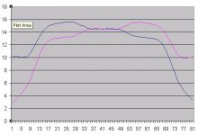
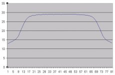
Bill F. said:However, since they were mirror-image and superimposed, they summed to an amazingly flat plot--the flattest I've ever personally generated. 🙂 Like the other motor, BL is around 29 Tm.
(Continued in next post...)
Your curve definitely looks good. But it looks like all you have is about 1" linear throw one way. I thought the whole point of doing this was to get huge excursions like the Parthenon. It seems to have the performance of a Brahma, but with the disadvantage of the motor being very expensive and very large.
Also, your total BL is very flat. But I still think you will have BL distortion. BL distortion comes from current (BLi). The current in either coil will see changing BL, and therefore may cause distortion, even though they are complimenting eachother. I remember in another discussion someone asked Dan Wiggins whether distortion levels would be similar to the Brahma if the Kms curve complimented the BL curve. In other words as BL was dropping, Kms would go up to make up for it and keep the coil linear. Dan mentioned that BL and Kms distortions will still be there. Although I'm not sure, I fear that this will be the case in your design as well, even though they are complimentary.
I'm not trying to knock your design. But I think you will have better luck just going with a more standard tripple gap XBL^2 motor. Or if you want to really go nuts, then go with 4 or 5 gaps. You could still probably use the neo magnets in the design. That would be interesting to see in an XBL^2 motor. Have one that has an Xmax of 100mm, but with only a 6" mounting depth.
Yes, Tom Danley of ServoDrive owns quite literally all the patents to servo loudspeaker technology... I believe they are getting close in age to expiring in the next few years, though.Variac said:There is a pro driver company that makes PA subs using a rotary servo motor (with a hollow shaft) IT is linked to 2 huge cones 180 degrees apart using I believe a Kevlar belt wrapped around the shaft.
Dan Wiggins knows Tom Danley personally. 😉
ServoDrive makes the BassTech7, and ContraBass units, both of which use a single Pacific Scientific servo motor to drive a rotary-to-linear motion converter, which in turn drives a pair of 15" cones.
(I think actually I referenced the ContraBass and BassTech7 earlier in this thread... something joking about using servos due to their linear BL curve... I don't think anyone got it. 😀 )
There used to be a wonderful website with some DIY information - and a fantastic Tom Danley whitepaper on servo loudspeakers - called "The ContraBass Corner"... but sadly, it's gone.
 Reward being offered for anyone who can find it, or at least the Tom Danley whitepaper.
Tom Danley also co-engineered a somewhat legendary woofer for Phoenix Gold - the Cyclone.
The Cyclone is the only rotary servo subwoofer to ever have been produced for the marketplace.
Hence, it's rare.
There's also an interesting little venture quietly existing out there called TWD Audio that exists out there... if you look, it's like a mini-ContraBass driver unit (12" cones rather than 15"), in a bandpass box, built for the car audio market.
I'm just speculating... but I find it suspicious that since no one can legally produce servo-powered loudspeakers without Tom Danley's (or ServoDrive's) approval, and since the company's name is TWD audio... just maybe possibly Tom Danley's middle name starts with a W? Little side venture? 😉
I honestly don't know, but it sure seems suspicious.
Here's a little information from my own web page you might be interested in:
A dissection of one of my Phoenix Gold Cyclone rotary subwoofers
My custom twin-motored DIY rotary SPL subwoofer project (still in progress)
Bill F. said:Hi Bryce,
Hey, was it you that was recently asking about my Lambda TD15X Apollos? If so, small world. 🙂
To answer your question, magnetic circuits are a tough thing to just walk into. But lemme tell you, when you begin to understand the nuts and bolts of what's behind the music you love listening to, it becomes great fun. 😎
There aren't really any great web tutorials or FAQs on motor design that I'm aware of, but I do recommend that you search for and download a neat little free program called FEMM. You can quickly build magnetic circuits of all shapes and types and see how the flux flows through them. I can't recommend it enough.
Other than that, just pay attention when people like Dan W. post. 😀
Hey Bill, yeah that was me. Was thinking about getting two more Lambda's, but decided not to do it at this time.
I'll check out that FEMM program. And I will just try to follow when all you smart people post. Try to pick it up from their I guess, and doing searches on different forums. Anyway thanks for your suggestion.
- Status
- Not open for further replies.
- Home
- Loudspeakers
- Subwoofers
- DIY Parthenon