It's hard to argue when your in the right!!!
I don't have to go and say that Dan has the design compromises stated in a nut shell. I've been sprinkling bits and pieces of it throughout the posts. It's good to have it in one nice concise statement ( or group of statements ). And from an acknowledged expert in the field to boot!!!
Having an ultra wide gap is both a boon and a bane. It might push back the idea of a bushing rod to guide this mess. And in keeping with the K.I.S.S. method it must be easy. Time to put my thinking cap back on. I'm running out of hair!!!
If we can keep the coil assembly in a state of obedience ( sit and don't move!!) then we can harness the potential flux in a more propulsive way pun tried. ( A word smith I aint )
I know that delrin ( or a competing low friction plastic, hell even a machined delrin bushing and a polished and waxed pole piece )can be had in sheet form and that it can be thermo formed. Maybe a coated pole and a double bushing on the ends of the former. Muuuuuhhhhahaaaaaaaaa. No I don't like that jacket with the long sleeves 🙂 🙄
Mark
P.S. Ground and polished tubing can be bought at any size you desire. Chrome plated even. Spanky!! and slippery. IT may be a way out of our problem.
some more findings...
No matter what I do I can't seem to get more than 4.5 T in the air gaps.
Geolemon, I tried a 3 gap version but still get only around the 4 T mark (yes, the same as the 6 gap). After a lot of playing I have concluded that the bottleneck is in the 10mm steal I'm modelling with. At this point I feel that simple rectangular steel tubing isn't going to allow high enough flux levels.
Cut everything down to one gap, and still only 0.7T. Those basic right angles are just not doing it.
Attachments
Square peg in a Round hole
If it doesn't work well using a square a thick walled tube can be cut in half. But Methinks that the real problem is that 1/2 of the area has no return path.
In the current offing the square tube has a hole bored in it and it is being used as a top plate/return path. Magnet placement on the return side may change that. Give it a try if you haven't.
Mark
Re: some more findings...
RHosch-
Thanks for the explanation, that does make sense, but only if you are cross-bracing the two diaphragms together... as opposed to just a perpendicular set of braces (parallel to the former), because then they'd just flex together.
Interesting thought...
But in the same sense, we could make a single diaphragm out of that, if it could prove more rigid in application...by literally sandwiching them together, meaning no need for bracing between the, which would again cut the weight back yet again.
But in that case, I'd have a tough time seeing how that would be stiffer than the truly single diaphragm, given each half of the sandwich being less than half the weight of the single diaphragm.
Do you think I'm thinking about this right?
How dramatically do things improve as you increase the wall thickness?
It would be discouraging to find out that we can't use our "junkyard wars" tubing solution. 🙁
There's just some cool-factor in that, IMO.
RHosch-
Thanks for the explanation, that does make sense, but only if you are cross-bracing the two diaphragms together... as opposed to just a perpendicular set of braces (parallel to the former), because then they'd just flex together.
Interesting thought...
But in the same sense, we could make a single diaphragm out of that, if it could prove more rigid in application...by literally sandwiching them together, meaning no need for bracing between the, which would again cut the weight back yet again.
But in that case, I'd have a tough time seeing how that would be stiffer than the truly single diaphragm, given each half of the sandwich being less than half the weight of the single diaphragm.
Do you think I'm thinking about this right?
I thought that the structural steel could be had in wall thicknesses up to 1 inch thick? That is what, about 25mm?Vikash said:No matter what I do I can't seem to get more than 4.5 T in the air gaps.
Geolemon, I tried a 3 gap version but still get only around the 4 T mark (yes, the same as the 6 gap). After a lot of playing I have concluded that the bottleneck is in the 10mm steal I'm modelling with. At this point I feel that simple rectangular steel tubing isn't going to allow high enough flux levels.
Cut everything down to one gap, and still only 0.7T. Those basic right angles are just not doing it.
How dramatically do things improve as you increase the wall thickness?
It would be discouraging to find out that we can't use our "junkyard wars" tubing solution. 🙁
There's just some cool-factor in that, IMO.
Hey you FEMM guys, look at this:
http://www.focal.tm.fr/gb/compo/archives/woofer/a_13kx.htm
Notice the neodynium magnets on the *outside* of the driver... notice the 1.07T gap strength If we use some kind of neodynium slugs in the outside part of the magnet structure, like this driver does, along with the neodynium-charged pole piece, we can probably better than double the flux level!
Given that the current favorite plan is based on square steel tubing, I vote for a different-shaped neodynium slug than what we use inside the pole piece; but, since I'm not doing any of the analysis, I could be totally wrong.
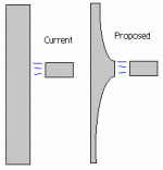
Hey, another question: the sides of the current pole piece are straight... what would happen if you curved them, so that in the parts where they're next to a gap, they're the 11mm away, but in other places they're farther away? Wouldn't this serve to strengthen the gap flux and improve linearity, at the cost of a little bit of excursion at the ends of the throw? Have a look at this illustration (and phear my mad pbrush.exe skillz)
http://www.focal.tm.fr/gb/compo/archives/woofer/a_13kx.htm
Notice the neodynium magnets on the *outside* of the driver... notice the 1.07T gap strength
If we use some kind of neodynium slugs in the outside part of the magnet structure, like this driver does, along with the neodynium-charged pole piece, we can probably better than double the flux level!Given that the current favorite plan is based on square steel tubing, I vote for a different-shaped neodynium slug than what we use inside the pole piece; but, since I'm not doing any of the analysis, I could be totally wrong.
Hey, another question: the sides of the current pole piece are straight... what would happen if you curved them, so that in the parts where they're next to a gap, they're the 11mm away, but in other places they're farther away? Wouldn't this serve to strengthen the gap flux and improve linearity, at the cost of a little bit of excursion at the ends of the throw? Have a look at this illustration (and phear my mad pbrush.exe skillz)
Attachments
Re: Re: some more findings...
Without ridges in pole piece (pointed):

With ridges in pole piece (flatter wider peaks):

DD's with equal surface area to a larger SD can have a combined stiffness >= SD and with less combined weight. This phenomenon occurs without bracing/connecting the diaphragms together as I understand it.geolemon said:RHosch-
Thanks for the explanation, that does make sense, but only if you are cross-bracing the two diaphragms together...
I've tried various sizes, up to 25mm, but there are no siginifcant advantages between the models I've done. I must wave my hands in the air though, for I'm far from an experienced modeller. I'm sure Bill, or ether FEMM users may be able to do a much better job.I thought that the structural steel could be had in wall thicknesses up to 1 inch thick? That is what, about 25mm?
How dramatically do things improve as you increase the wall thickness?
I've always liked those 🙂 But that's 1.07 T in a single gap, probably in a much reduced gap width, and not restricted by machining/material availability.Nappylady said:Notice the neodynium magnets on the *outside* of the driver... notice the 1.07T gap strength
This is a valid technique in my (short) experience. But again I'm restricting designs to what can practically be accomplished. Adding simple ridges in the pole piece will probably be a must (See diagrams). But greatly increasing the flux density it won't.Hey, another question: the sides of the current pole piece are straight... what would happen if you curved them, so that in the parts where they're next to a gap, they're the 11mm away, but in other places they're farther away? Wouldn't this serve to strengthen the gap flux and improve linearity, at the cost of a little bit of excursion at the ends of the throw? Have a look at this illustration (and phear my mad pbrush.exe skillz)
Without ridges in pole piece (pointed):
With ridges in pole piece (flatter wider peaks):
Just throwing out another tidbit... it seems 1" cubes of NeFeb are pretty inexpensive. Perhaps they could be stacked together in some arrangement to increase flux. Really have no idea... seems the motor design is going to be primarily limited by what magnet shapes are readily available.
I hope I'm wrong, but after playing around with it all day, I have to conclude that using two stacked magnets to saturate three 12mm+ gaps (say ~0.8 T) is just not doable with those magnet/pole sizes. I'm beginning to see how the distributed magnet approach was reached for the Parthenon.
If I read correctly (please confirm Dan), then ideally we require magnet surface area, and since in the current config the magnets are in the pole piece, we are limited by the pole diamater, and stacking doesn't have the same effect as increased surface area.
I did a quick FEA test using 1" thick steel tubing and appropriate pole thicknesses.
Test 1:
Mag dimensions: 238mm x 10mm = (2380mm2)
B: 0.6 T in each gap
Test 2:
Mag dimensions: 48.8mm x 48.8mm (2380mm2)
B: ~0.4 T in each gap
So back to the drawing bored, unless ~0.4 T is sufficient (regardless of 3 or 6 gaps), or a 0.46m+ pole piece is acceptable 😀. Again, I could be wildly wrong. Only time, and Dan will tell...
I misjudged Nappylady's identification of a good approach: using multiple small mags outside the pole piece. Thus the cost is kept down and the topology allows greater flux then some big momma magnets trapped in the pole piece (in fact this is inline with the first motor I ever designed 😀)
Linear Motor?
Shouldn't there be a break-even point, when Xmax is so large, that a linear motor design would make more sense then the traditional voice coil?
Any ideas what something like this does cost:
http://www.aerotech.com/products/motors/blm.html
Regards,
Peter Jacobi
Shouldn't there be a break-even point, when Xmax is so large, that a linear motor design would make more sense then the traditional voice coil?
Any ideas what something like this does cost:
http://www.aerotech.com/products/motors/blm.html
Regards,
Peter Jacobi
Vikash,
You're getting it now...🙂 There's a reason we went with a lot of smaller magnets. Easier to assemble (not too many people have chargers capable of charging N40 neo laying around), higher flux densities, and actually lower cost per unit flux...
A lower flux like 0.4T can be fine. I don't think people have decided what they want in the motor, so until some basic design goals (even a first cut like T/S parameters) are set, it's kind of hard to design a motor.
Also, you can see why we use the grooves in the pole piece - they really help square up the B fields in the gap, which helps immensely with flat BL curves. Going with a straight-sided pole loses a lot of the advantage one gets with a multi-gap approach.
Dan Wiggins
Adire Audio
that a linear motor design would make more sense then the traditional voice coil?
Boy, I wonder. That would sure be easy. Remember the Servodrive people use rotary motors. And at the price of the Parthenon, $2000 for a linear motor looks like a bargain. Only problem is I made up the $2000 number 😀 😀
Someone has to find out
The Parthenon will cost you more like $4K-$5K. 😉
I'm a little confused about the statements regarding the neo magnets..
I thought we WERE creating a little neo sandwich here, using multiple neo magnets sandwiched between our "top plate assembly" and the back plate?
Not stacked, mind you, but distributed across the surface area, between the top plate assembly and back plate?
I was assuming we'd cover as close to every square mm if we had to, to get the flux to a reasonable level in the gap.
What magnet strategy was used for the FEMM plots posted earlier?
Sorry for being a little off topic, but where did you guys learn all this stuff. I would like to be able to understand this stuff more and get in on the action and follow your discussions better. Are there books? Just learn as you go or from other people? Just basically I would like to know a little bit about all things about the motor and their different effects. And how that translates to easy to understand terms, like this will make it have more xmax or sound cleaner, etc. Any information will be appreciated.
Thanks
Thanks
Hi Bryce,
Hey, was it you that was recently asking about my Lambda TD15X Apollos? If so, small world. 🙂
To answer your question, magnetic circuits are a tough thing to just walk into. But lemme tell you, when you begin to understand the nuts and bolts of what's behind the music you love listening to, it becomes great fun. 😎
There aren't really any great web tutorials or FAQs on motor design that I'm aware of, but I do recommend that you search for and download a neat little free program called FEMM. You can quickly build magnetic circuits of all shapes and types and see how the flux flows through them. I can't recommend it enough.
Other than that, just pay attention when people like Dan W. post. 😀
The Parthenon will cost you more like $4K-$5K
That's Peter's point, even if the linear motor is $2k it might be a bargain. Anyone know if a linear motor has so much inertia to
be incompatible with this subwoofer use?
here's some in the $700 range:
http://www.mcmaster.com/
Page 894
It's max speed is 134 in/sec - does this work?
let's see: 20 hz and 4" stroke is 80 in/sec I guess. Maybe marginal, given acceleration time. and direction reversal.
This one from Peter's link is 20 meters/sec:
780 in/sec Now that's pretty fast!
http://www.aerotech.com/products/motors/blmuc.html
Variac said:
[...]
It's max speed is 134 in/sec - does this work?
let's see: 20 hz and 4" stroke is 80 in/sec I guess. Maybe marginal, given acceleration time. and direction reversal.
This one from Peter's link is 20 meters/sec:
780 in/sec Now that's pretty fast!
http://www.aerotech.com/products/motors/blmuc.html
Is 4'' peak to peak or one direction?
Assuming p-p:
v(max) = pi * frequency * X(p-p) = 250 in/sec
Regards,
Peter Jacobi
Now that I started my contributions to this thread, as if it were the NASA workshop on unconventional earth to orbit systems, I can continue as well:
Short of DIYing the linear motor, there seems to another option for an unconventional long throw driver:
Step a) Make the VC long, keep the magnet air gap reasonable short.
-- This alone has a lousy efficency, I know this. --
Step b) Make the long VC into a number of short, individually connected pieces, so that about 2..3 of them are simulatanously in the air gap at any time.
Step c) Add electronics to drive the current only through the segments , which are in the gap. Use some extra sensor to let the electronics know, which to drive -- or detect the change in magnetic field at the VC-segment leaving the gap, by measuring the current.
Regards,
Peter Jacobi
Hope you all had a good weekend!
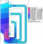
I spent a few hours of mine tweaking models and running simulations, so now it's sharing time.
A few posts ago, Dan W. made a case for a motor topology with three gaps and one coil. I agreed with him in principle, but I have also been flirting with the less-conventional 6-gap, 2-coil DDD topology (essentially a symmetric siamesed arrangement of the conventional motor in which the VC passes completely through, allowing spiders and potentially diaphragms on both sides of the motor).
So I decided to optomize both topologies and bench race them.
I chose a common set of denominators:
--Identical coil lengths, spacings, and 0.8" sq. total coil cross sections (=same wire and number of windings in the real world)
--4.24" dia. poles of 1018 steel
--1/2" 1018 steel return circuits
--Identical NdFeB ring magnets
--1/10" minimum clearance on both sides of coil/former
--1/10" former wall thickness
I started with the conventional tri-gapper.
2/10" clearance + 1/10" former + 2/10" coil thickness gave me 0.5" gaps, very close to what Dan recommends.
When I put the model through its paces and generated a BL plot, it looked like this:
(Continued in next post...)
Attachments
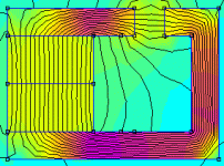
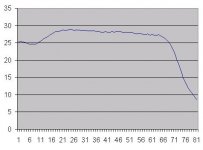
As you can see from the plot above, flux flow seems to diminish as the voice coil progressed from inner gap to outer. (The degree of change suprised me. I suspect it may be a compromise of the 1018 steel--I'm still learning.🙂 )
In an effort to flatten the BL curve, I spaced the inner gap at 0.7", and the middle at 0.6"
(Continued in next post...)
In an effort to flatten the BL curve, I spaced the inner gap at 0.7", and the middle at 0.6"
(Continued in next post...)
Attachments
- Status
- Not open for further replies.
- Home
- Loudspeakers
- Subwoofers
- DIY Parthenon