This is exactly what I wrote about in my post 5488 about synchronizing two cartridges.The pauses between tracks would begin earlier for the reading arm and would end earlier too.
But Carlo did not consider this a problem (5489).
Let's see what solution he has.
I have my own solution.
I would be delighted and intrigued to see your solutions Andrey, and any others out there.
I consider this forum as the place where you offer up your good thoughts and advice as early as possible to help others.
Sometimes i am wrong, quite often in fact, but that's OK! - i learn.
Lots of people have helped me enormously that way and i hope if you join in that way you will find it a very constructive and respectful place!
What do you think will help in Carlo's development please?
M
Thanks for the reply, Mike.Hi Paul, i built numerous experiments without any machining equipment at all, and i am sure many others the same.
Don't be daunted by that!
I chose non recirculating balls on anodised aluminium rails to avoid recirculating ball bearings and glass rails (where i also started).
Its an elegant and simple solution allowing low resistance with simple bought in parts.
M
For the rails, do you mean something like these?
Linear Motion Shaft: Ceramic coated 6061 Aluminum
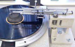
My first prototype, though I'm not even sure I'd call it that, more like an investigation of concept is pictured below. It uses a glass tube and these bearings:
3/16x3/8 ceramic ball bearing
Is that the sort of bearing you're talking about? If not, could you please elaborate (link, picture or description)?
It seems to me that there are 2 material (as opposed to design) upgrades from my current prototype. The first would be a tungsten carbide rod. I'm not sure where I'd buy this or if it would require machining I cannot perform. The second would be a jewel bearing design. What I've seen off the shelf is a bespoke design based on parts from a vendor like this:
Swiss Jewel
Is this the sort of thing we're talking about? These parts seem very small and fragile. Am I wrong about that? I'm also not clear which parts I would use and I don't know what I'd use as a disc or wheel.
Initial "investigation of concept"
BS TwinArm
The angular difference (always referred to their own pivots, not reciprocal) between two tips on the same groove can be reasonably managed, imo, as indicated in the answer to Alighiszem.
Even in the case of a considerable distance between the two (view the attachment of a "wrong" situation), the "timing difference" becomes just the matter of where you place the starting point on the first pulley of the "proper ratio connection"
What instead imposes the minimum distance of the two tips is the possibility of eccentrics on disc, which would lead to serious problems, up to skipping. This is the "small detail", "the elephant in the room" I mentioned from start.
This strange hypothesis is certainly complex and difficult to understand; and the more I go on, the more I realize how large is the "elephant family", and how concentrate must i be on real priorities. (Eg - i was calculating the relative motions basing on torque, while i've now realized to take care the overall work, instead.
Therefore, there is no point in wasting your time.
Thanks to all for precious help and interest. I will let you know
ciao - carlo
Attachments

Hello Carlo,
Interesting idea. But maybe the elephant in the room isn't an elephant at all, but an ANT, an ELEPH ANT, no?
Ralf (likes to play with words)
Interesting idea. But maybe the elephant in the room isn't an elephant at all, but an ANT, an ELEPH ANT, no?
Ralf (likes to play with words)
Thanks Ralph, we "gadget builders" understand each other right away.
This road is full of stumbles and pitfalls, I don't know if I can get to something.
So better to be careful of the dangerous holes, the small ants can be crushed without remorse; otherwise while looking at the ant you'll fall into the hole.
c (likes to play with words too, but in italian unluckily, so often at risk to offend someone)
Last edited:
Might you also offset the angular difference of the eccentrics through the drive train, is it possible to lag the drive to the RTA by the correct angle through the pulley mechanism (so coincident styli is not an elephant) as well as cope with the arc to straight line effect?BS TwinArm
What instead imposes the minimum distance of the two tips is the possibility of eccentrics on disc, which would lead to serious problems, up to skipping. This is the "small detail", "the elephant in the room" I mentioned from start.
ciao - carlo
M
I wrote this after a glass of Shiraz, so may be complete rubbish, in fact same as before the glass!
Paul, i didn't wish to leave you out there with no answers too long, but its the golf season, not the tonearm season here.Thanks for the reply, Mike.
For the rails, do you mean something like these?
Linear Motion Shaft: Ceramic coated 6061 Aluminum
My first prototype, though I'm not even sure I'd call it that, more like an investigation of concept is pictured below. It uses a glass tube and these bearings:
3/16x3/8 ceramic ball bearing
Is that the sort of bearing you're talking about? If not, could you please elaborate (link, picture or description)?
It seems to me that there are 2 material (as opposed to design) upgrades from my current prototype. The first would be a tungsten carbide rod. I'm not sure where I'd buy this or if it would require machining I cannot perform. The second would be a jewel bearing design. What I've seen off the shelf is a bespoke design based on parts from a vendor like this:
Swiss Jewel
Is this the sort of thing we're talking about? These parts seem very small and fragile. Am I wrong about that? I'm also not clear which parts I would use and I don't know what I'd use as a disc or wheel.
Initial "investigation of concept"
View attachment 1473096
I admire that you have put something together and put your hands on it to get a feel of things.
I found that was the way i understood a few of the critical matters.
Many folk on the thread gave me great ideas and encouragement, not least Carlo, Warren, Niffy and Karsten, please excuse me, those i left out!
Then i was encouraged to measure the results. initially i resisted that idea..........
Every time i listened to something which took a lot of hard work it always sounded better, but measurements didn't always support that perception.
So lots of kit went in the old parts bin!
Frequently strongly advocated ideas, carefully developed, measured poorly, so i learnt a bit about my process.
There are many different routes to achieve some quite good sound.
What lights your fire?
I quite like the idea that i made it and it cost little so i don't use expensive materials like carbide etc.
I cannot build a cartridge so i use a quite expensive old MM cartridge and my silly old arm sounds and measures quite well with it
I happen to have a quite well respected conventional proprietary TT/arm combination which sounds fine and has attracted good reviews.
My home made set up sounds as good and measures significantly better.
That generates a certain satisfaction.
What ambition do you have?
You can go and buy two good tonearms for you and your son, but what would you like to achieve instead?
M
Now i will seek out some pictures etc to answer the questions you asked me, and welcome to the forum from me where i hope you will enjoy the welcome and constructive responses that some folk will and can give you! - there is some great thinking out there.....
.....is it possible to lag the drive to the RTA by the correct angle through the pulley mechanism..... #5507
Imo, even after a cup of strong coffee, it is damn complicated, if not impossible.
If eccentrics were at fixed distance it could be managed as in my graph #5504, but they are never the same (especially on the two sides, and therefore there is an additional variable that my twin neurons refuse to manage, if not as you indicated with the strict proximity of the two tips.
However, if there were a smart solution, this thread is certainly the place where someone would indicate it.
Back to TwinArm work - carlo
Last edited:
The Russians have a saying that roughly translates into English as: don't rush into the fire before your father.I would be delighted and intrigued to see your solutions Andrey,
The meaning of the saying is that you shouldn't teach someone who is more experienced.
I think Carlo has thought about his idea for a long time and has a solution to the problem.
The problem is how to make the needle follow the middle of the groove and provide equal pressure on each side of the groove at eccentricity.
Are you asking me to improve on perfection?What do you think will help in Carlo's development please?
AG.
Hello Paul,It uses a glass tube and these bearings:
3/16x3/8 ceramic ball bearing
I mentioned "the below" in another thread but was ignored.
You are running the bearings on their edges, which in my opinion is not a good idea because the edges have no precision.
The outer race of a ball bearing is machined in a screw machine and is made slightly over-size. This is called a blank. Next it is heat treated and precision ground. When the blank is first machined, the edges of the outer race receive a chamfer. This chamfer has nothing to do with the precision of the finished bearing and its only purpose is, to allow assembly into a precision counter bore that may not have sharp corners at its bottom. This chamfer has a
lathe-finish, is not ground and may not even be concentric to the outer race. If I were a ball bearing and someone would run me on my chamfers, I would consider that a slap in the face 🙂
It is kind of cool to use carbide rods and you may find them at the McMaster-Carr website. But I think that, heat treated 440-c stainless steel would be sufficient.
Of course, the rod should be hard but what is also important is, what is called the "lay" of the surface of the material. The precision rods that I am familiar with, are centerless ground and that operation leaves groove-like toolmarks PERPENDICULAR to the center line of the rod. Depending upon the quality of the ground surface, a ball bearing could easily be impeded by those tool marks. Therefore, whatever rods you use, they should be longitudinally polished or lapped.
I hope that, I have helped and not discouraged you.
Ralf
I searched around for some pictures Paul, but found nothing illuminating, so i dug out some old bits from the scrap box and took some snaps for you.Thanks for the reply, Mike.
For the rails, do you mean something like these?
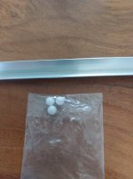
Here you can see the very simple bearing types i use.
These are old scraps, not actual parts, hence the dirt and scratches etc.
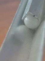
The balls are 5 or 6mm ceramic balls, best tolerance you can get is normally G10, but G5 or 3 would be slightly better.
The rails are anodised aluminium angle, so is the carriage, all cut and fettled to suit your design.
Flat, hard anodised aluminium angle is difficult to find, but inexpensive!
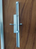
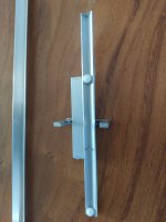
On the runner/carriage, you can see how the balls are retained in place, and they travel one end to the other, the nature of the travel, the carriage will travel twice as far as the ball. please ignore the bits glued on and cut off, its just a bit of scrap
When set up, i simply move the carriage to the ends of its travel a couple of times to and fro and the balls then stay in the correct sequence/positioning as the carriage works.
This way, you wont have any rattling unloaded balls, no ball skidding and can use alternative rails etc if you wished. a pair of glass rods are also fine but in my experience less flat.
I have measured the resistance with my set up which has a stabilising rail as well and i achieve resistance only slightly more than Niffy with the jewelled bearings etc.
That suits my miserly approach to purchase of parts, my whole arm set up with lots of spare material left over costs around £20.
Attachments
And i see Ralfs useful answer came in while i was typing. All relevant comments as well in terms of using enclosed ball bearings.
M
I have spent many hours with the polishing wheel on various projects. anodised is less useful in this case as you will most likely polish through the coating before getting it flat, but i have used a pair of polished stainless rods on some of mine, three in this case as i have a stabiliser
M
I have spent many hours with the polishing wheel on various projects. anodised is less useful in this case as you will most likely polish through the coating before getting it flat, but i have used a pair of polished stainless rods on some of mine, three in this case as i have a stabiliser
Attachments
Fully quote Ralf #5511
+ Geometry and correct application of forces are more important than materials and finishing, by several orders of magnitude.
First design rationally and then build correctly, the best we can
Solitary grumbling - c
(graphs instead not mine)
+ Geometry and correct application of forces are more important than materials and finishing, by several orders of magnitude.
First design rationally and then build correctly, the best we can
Solitary grumbling - c
(graphs instead not mine)
Attachments

My ambition is to be able to design and build an arm with the following requirements:Paul, i didn't wish to leave you out there with no answers too long, but its the golf season, not the tonearm season here.
I admire that you have put something together and put your hands on it to get a feel of things.
I found that was the way i understood a few of the critical matters.
Many folk on the thread gave me great ideas and encouragement, not least Carlo, Warren, Niffy and Karsten, please excuse me, those i left out!
Then i was encouraged to measure the results. initially i resisted that idea..........
Every time i listened to something which took a lot of hard work it always sounded better, but measurements didn't always support that perception.
So lots of kit went in the old parts bin!
Frequently strongly advocated ideas, carefully developed, measured poorly, so i learnt a bit about my process.
There are many different routes to achieve some quite good sound.
What lights your fire?
I quite like the idea that i made it and it cost little so i don't use expensive materials like carbide etc.
I cannot build a cartridge so i use a quite expensive old MM cartridge and my silly old arm sounds and measures quite well with it
I happen to have a quite well respected conventional proprietary TT/arm combination which sounds fine and has attracted good reviews.
My home made set up sounds as good and measures significantly better.
That generates a certain satisfaction.
What ambition do you have?
You can go and buy two good tonearms for you and your son, but what would you like to achieve instead?
M
Now i will seek out some pictures etc to answer the questions you asked me, and welcome to the forum from me where i hope you will enjoy the welcome and constructive responses that some folk will and can give you! - there is some great thinking out there.....
- Should be a linear tracker. I've used both and really prefer them
- Does not use an air bearing - I don't want to deal with air pumps
- Price of parts below $400 (flexible) per arm
- Doesn't require machining or other processes / equipment - I can do wood and acrylic / polycarbonate machining and very basic softer metal work
- Sounds very good - doesn't have to be state of the art with respect to sound quality
- Should "just work" on flat records once properly set up. Shouldn't need tweaking or be finicky
- Has good ergonomics and can be made with high aesthetics (this includes not being too large)
- Timeframe is quick - I really want something finished fairly soon (say, 4 months max). I don't want a research project. That might come later for myself
I had followed this thread when it first came out and made a mental note to come back to it when I could act on it. Since then, it has progressed way beyond it's beginning. Is this because the initial design had problems or has it just been ongoing improvements and/or research? I'm wading through the thread again (on page 30), but obviously it's quite a long read.
Hi Ralf,Hello Paul,
I mentioned "the below" in another thread but was ignored.
You are running the bearings on their edges, which in my opinion is not a good idea because the edges have no precision.
The outer race of a ball bearing is machined in a screw machine and is made slightly over-size. This is called a blank. Next it is heat treated and precision ground. When the blank is first machined, the edges of the outer race receive a chamfer. This chamfer has nothing to do with the precision of the finished bearing and its only purpose is, to allow assembly into a precision counter bore that may not have sharp corners at its bottom. This chamfer has a
lathe-finish, is not ground and may not even be concentric to the outer race. If I were a ball bearing and someone would run me on my chamfers, I would consider that a slap in the face 🙂
It is kind of cool to use carbide rods and you may find them at the McMaster-Carr website. But I think that, heat treated 440-c stainless steel would be sufficient.
Of course, the rod should be hard but what is also important is, what is called the "lay" of the surface of the material. The precision rods that I am familiar with, are centerless ground and that operation leaves groove-like toolmarks PERPENDICULAR to the center line of the rod. Depending upon the quality of the ground surface, a ball bearing could easily be impeded by those tool marks. Therefore, whatever rods you use, they should be longitudinally polished or lapped.
I hope that, I have helped and not discouraged you.
Ralf
I agree about running the bearings on their edges. I only did this because that's how the original design (back before page 30) worked. Frankly, I never understood about the brass sleeves and the looseness of the bearings described there and it worried me that the design seemed to require that. So, I think I will do a redesign so that my bearings run along their outer races despite this making for a more complicated carriage. Still giving thought to how to do this.
I also hear you about the tooling process of the rod, but unfortunately, this depth of information doesn't seem to be available from typical source. These are described as polished, ground and turned:
440C Stainless Steel Linear Motion Shaft
I don't know if those would have the problem you describe.
Has anybody thought about a linear tracking arm, where the bearings run in an oil filled trough?
Hello Icsaszar,
Would the bearings still run on rods/tracks though?
Years ago, I came across a Japanese patent where the tone arm was attached to a float on a bath of oil. The details were pure genius.
The bottom of the oil trough had three channel-like depressions filled with mercury and the tone arm float had three electrodes that dipped into the mercury for signal transmission. To stop the float from rubbing on the edges of the trough due to the record drag force, repulsing magnets were installed on the tone arm float and the adjacent wall of the oil trough.
Ralf
Last edited:
Hello Paul,Still giving thought to how to do this.
A number of years ago I developed a tone arm carriage with a number of ball bearings that ran on their ground faces. I will look at that design in my computer later Today and let you know what I did.
Ralf
Non recirculating balls running on tracks would be simple, ensure constant contact and grounding, ensure balls run on flat surfaces, locate accurately, remove any potential for rattles from enclosed ball bearings all in one.............the tracks can be steel rods if desired/selected.
If you were to handle a few of these parts you would soon get the feel for them. I still have all the old enclosed ball bearings etc before I moved on to non recirculating balls on tracks.
If you were to handle a few of these parts you would soon get the feel for them. I still have all the old enclosed ball bearings etc before I moved on to non recirculating balls on tracks.
- Home
- Source & Line
- Analogue Source
- DIY linear tonearm