Hi Jim,
Of your collection of cartridges the A90 is the one I covet the most. The A90 being mid compliance would suit a lighter arm than your current creation, 80g is just about perfect in my books. Your last air bearing arm? I'm sure you said that about your last arm.
Niffy
Of your collection of cartridges the A90 is the one I covet the most. The A90 being mid compliance would suit a lighter arm than your current creation, 80g is just about perfect in my books. Your last air bearing arm? I'm sure you said that about your last arm.
Niffy
ahh. OK.
If only we could move the whole contraption vertically just like typical pivoted tonearm ? I think a parallelogram type of assembly where rails (on which pulleys run) would be on one side and counterweight on other. Probably would be complex. And with more friction too.
Thanks and regards.
Hiten,
Pulleys are not good idea. As I said before, I tried actually on my ball bearing linear arms years ago. It compressed the sound. I finally realized that a good linear or pivot arm must allow the cartridge follows natural interactive movements between stylus and groove. Any force to disturb such movements will degrade the sound. Pulleys add extra forces and disturb the natural state of cartridge. I think they will create generator misalignment (GM, Niffy's term).
Jim
I believe it depends on the weight U used and where the thread is connected to the carriage. The original idea was with the pulley to add just enough weight to protect the cantilever overload (bending etc). I will test it but only sometimes at next spring or summer. A lot of work has to be down until I can test. 🙂
There are problems of using a falling weight and pulley to bias bearing friction.
Almost all records have some degree of eccentricity. This means that the cartridge spends almost as much time moving to the right as it does to the left, typically 45% of the time the arm is moving to the right, average record. A bias weight that cancels bearing friction for leftwards motion will effectively double friction to the right. You can't have separate bias weights for left and right motion as they will cancel each other. The thread has to pass over a pulley which will require its own bearings that will have its own friction.
It is theoretically possible to make a bias system to counter bearing friction. The first thing that is required is to implement a record centering system that elliminates eccentricity. Rather than using a falling weight simply slope the rail towards the center of the record. The slope would have to be at the right angle to exactly match the dynamic friction of the bearing. This would mean that VTA would decrease as the record played. This could be countered by having a conically dished platter with the angle of the dish matching the slope of the rail. A screw down clamp would force the record to conform to the platter. This has the added advantage of being quite effective at reducing warps. No strings, pulleys or anything else to interfere with the operation of the arm.
One hell of a lot of work just to eliminate the last little bit of friction. If you're that fanatical about minimising friction it would be a lot less work to just build an air bearing arm.
The record centering device would still be nice to have.
Niffy
If only we could move the whole contraption vertically just like typical pivoted tonearm? I think a parallelogram type of assembly where rails (on which pulleys run) would be on one side and counterweight on other. Probably would be complex. And with more friction too.
I think for strictly vertical movement it might work with parallelogram type. It's similar in concept to Carlo's invention, except the horizontal carriage needs to be much smaller and lighter and I would suggest the mini floating headshell like Ralf/Straight Tracker's tonearm sliding on a 5" rail, which covers the groove area of an LP.
I really think there are multiple ways to arrange a parallelogram type of arm and the above is just one of them. Here's another very rough idea.
I believe it depends on the weight U used and where the thread is connected to the carriage. The original idea was with the pulley to add just enough weight to protect the cantilever overload (bending etc). I will test it but only sometimes at next spring or summer. A lot of work has to be down until I can test. 🙂
In fact, I tried different weights, balanced weights and unbalanced weights. If you want to prevent over shot, a silicone though is much more effective and less intrusive. However, for ball bearing linear arm, it's bearings have enough friction already. It is not necessary to have additional damping.
I will be happy to see your test results here.
Jim
There are problems of using a falling weight and pulley to bias bearing friction. <snip>
Great explanation, that makes sense. Thank you.
Niffy, Super10018, Directdriver
by pulleys I did not mean regular bearing, plain pulley or bias pulleys. Here is little rough drawing of what I was thinking for Vertical movement of Short toneram.
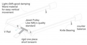
A Niffy type of high quality short tonearm will be on V rails which is connected by two wands with Counter balance. The short tonearm is in one piece with no liberty for vertical movement. When a warp occurs, the whole assembly will move upwards and in addition, pulleys will exert slight force tangent (shown by Blue arrow) to V rail which also helps. And because we have balanced with counterbalance it will only require very little warp force for vertical movement provided the knife bearing have very low friction. Picture is just to show concept. Not to be taken literally as is.
Regards
by pulleys I did not mean regular bearing, plain pulley or bias pulleys. Here is little rough drawing of what I was thinking for Vertical movement of Short toneram.
A Niffy type of high quality short tonearm will be on V rails which is connected by two wands with Counter balance. The short tonearm is in one piece with no liberty for vertical movement. When a warp occurs, the whole assembly will move upwards and in addition, pulleys will exert slight force tangent (shown by Blue arrow) to V rail which also helps. And because we have balanced with counterbalance it will only require very little warp force for vertical movement provided the knife bearing have very low friction. Picture is just to show concept. Not to be taken literally as is.
Regards
Attachments
Last edited:
Hi Hiten,
Unfortunately I can see several problems with your design. I cannot see any mechanism to prevent the carriage pivoting in the rail. What you basically have is two vertical pivots, one at the rail and one with the knife edges.
A design like this will inherently have very high vertical effective mass. The entire mass of the rail and carriage is very close to the stylus's location so virtually their entire mass will contribute to the vertical effective mass.
Less of a problem but still a problem is how to move the arm out of the way when changing records.
Sorry to put a bummer on your design, it's better to discover problems at this stage rather than after putting in hours of building work . If there is any help or advice you require please feel free to ask and I'll do my best to answer.
Niffy
Thanks Niffy,
I did assumed the whole contraption weight will be increased so I put in light stiff damped wands as mentioned in the picture. Actually I don't like complicated tonearms. The exercise was to see possibilities. I also thought of problems of record changing, but did not post that point as I thought if concept was worth, it can be further improved later. For example the whole thing can neatly be arranged like Technics SL series (Briefcase type) arrangement.
Here is one mechanism.
Link.
I wonder if it can be given more consideration. Most of the time the red line is straight. But with 10 pivots/bearings it will be terrible. But just posting regardless because I guess such things/concepts might generate some other ideas.
Regards.
Hiten,
If you have the pulleys which have low fictions same as jewel bearings, I don't know why you need to add other pivots. However, I don't know if this kind of pulleys exist. You are designing based on something doesn't exist.
Jim
If you have the pulleys which have low fictions same as jewel bearings, I don't know why you need to add other pivots. However, I don't know if this kind of pulleys exist. You are designing based on something doesn't exist.
Jim
Last edited:
by pulleys I did not mean regular bearing, plain pulley or bias pulleys. Here is little rough drawing of what I was thinking for Vertical movement of Short toneram.
Sounds like a semantic thing. There's no pulley in your drawing so I suggest not use that term. Carlo drew up a similar design in post#2368 but his carriage does not pivot. Yours have double vertical pivots. You need something to inhibit vertical movement of the rollers and use the pivot bearings for that. You do not even need a short arm. If you add an extra wheel, a tricycle like carriage, will do it.
Gentlemen,
Pardon me as I didn't linked it to my previous post few pages back. This was not a concept for 'New Linear mechanical tracking tonearm design'. The gist of all this is if we have linear tonearm design where the tonearm wand is long and the driving mechanical system* far back; the travel line that Cartridge+stylus follows (also to and fro motion for eccentric records) may 'present' pressure 90 degrees to the drive mechanism as shown by blue arrows in post #2536. So if we can somehow design a mechanism which moves the stylus across 'in line as much as possible to the stylus path' across the record we may have slight advantage of lowering resistance/friction in operation.(Shown by dotted red arrow in same post) But as niffy said we need easy vertical motion too for short wands. So my effort was in that direction. 🙂
*which could be any design.
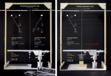
Measures as usual, but this time the results from my digital scale method were so random that i've recovered my pendulum set up used for the stylus drag measures, modified according (hopefully) to the description that Niffy gently gave me .
In short we use an "inverted pendulum", measuring the displacement of the constraint to calculate the potential energy, and then the Force needed to move the carriage: quite tricky, average of several needed.
Conditions used L = 0,35 m ; m = 0,0045 Kg (SI units)
With Lil Casey the constraint must be moved 22 mm > 3.60° theta angle): if calcs are not mistaken F = 0,141 mN.
Frankly better than expected, since linear ball bearing coefficients of friction are said 0,002 ca: 14,5 gr weight, cartridge included, and just 4 balls are doing their job.
Tested alike, the JR Casey (#2360 normal linear with the same bearing) needs - 0,375 mN, the Rabbit PLT - 0,254 mN (but PLTs use more the SD than SF). when my Unipivot is on - 0.052 mN.
This test seems more a measure of stiction, than of friction.
In fact, once stopped the string constraint (beginning of movement), the carriage does not maintain that angle, instead almost realigns on the vertical. The friction seems much smaller than the stiction.
Much smaller? fantastic! Not so, imho: the carriage travels about 90 mm in 30', very slow uniform motion. But what happens on eccentricity? Let's take a limit case, 1 mm, (Riaa standard <1.27). In less than 2" the carriage must stop - go back 1mm - stop again and go forward 1mm (20 times faster). Think this in terms of stictions and accelerations.
Now the vertical movement: that simple gadget (two levers at 90°, rotating on a bearing) allows a measurement with the same effective method. Result = 75 mm movement - 12,4° theta angle = 0,487 mN
Again better than expected and seen during the "crash test". Maybe the inertia plays a role not shown in this test. Improvement needed
carlo
P.S. This method, using an even smaller mass, could maybe (maybe!) work to measure the elusive skating force. With the arm in motion measure the "skipping force" on the right and on the left. The difference should be the result.
Attachments
Last edited:
Hi Carlo,
Great test rig. It looks very similar to the rig I made for testing my bearings. On my rig I moved the hanger that the pendulum hangs from using an M3 threaded bar. One full rotation of the bar moves the pendulum by half a millimetre allowing easy, accurate and repeatable measurements. For each test I would take many readings. I could then use this information to not only determine the average friction of the bearing but also how consistent the bearings are. My jewelled bearings gave readings that were all very similar showing that the bearings had a high level of consistency. The ball race bearings gave readings that covered a wide range showing poor consistency.
There are two types of friction, static friction (stiction) and dynamic (moving) friction. As the force is increased from zero the carriage won't move until it is great enough to overcome the static friction. Dynamic friction is always lower than static friction so once the force is great enough to start movement the carriage will continue to move and the force required to keep it moving will be lower. The deflection of the cantilever will be greatest just before the carriage starts to move. Once the carriage starts to move the deflection will decrease. My test rig only measured static friction.
Due to eccentricity the carriage is constantly stop-starting in its motion. Every time the carriage stops it has to overcome static friction before it starts to move again. As static friction causes the greatest cantilever deflection it is of greater importance.
If you have a record that has an eccentricity that is less than half the groove pitch (>40-50um) then the carriage will not be stop-starting but will move constantly , with very slightly changing velocity. In this case it will only be dynamic friction that has an effect so cantilever deflection will be reduced. Deflection will be reduced further in this case as the inertia of the carriage won't play a role.
Niffy
Gentlemen,
Pardon me as I didn't linked it to my previous post few pages back. This was not a concept for 'New Linear mechanical tracking tonearm design'. The gist of all this is if we have linear tonearm design where the tonearm wand is long and the driving mechanical system* far back; the travel line that Cartridge+stylus follows (also to and fro motion for eccentric records) may 'present' pressure 90 degrees to the drive mechanism as shown by blue arrows in post #2536. So if we can somehow design a mechanism which moves the stylus across 'in line as much as possible to the stylus path' across the record we may have slight advantage of lowering resistance/friction in operation.(Shown by dotted red arrow in same post) But as niffy said we need easy vertical motion too for short wands. So my effort was in that direction. 🙂
*which could be any design.
Hi Hiten,
With any design it is a balance of compromise.
As arm length is reduced the torsion trying to twist the carriage on its bearings will reduce and this should make it easier for the carriage to move. (Reducing bearing friction will also reduce it's torsion.) The main advantage of reducing arm length is that the arm becomes more rigid. (For a straight tube rigidity is inversely proportionally to the third power of its length so if you halve the length you increase rigidity eight fold) The single biggest source of colouration with most arms is due to the bending mode resonances of the armtube. Increasing rigidity helps to control these resonances. A short arm also deals with compression waves much better as the delay of any reflections is shorter. As shorter arms need smaller counterweights the strength of reflections of the counterweight is also reduced. All of these effects means that as the arm length is reduced the sound quality improves.
However.
As arm length is reduced the effects of record warps becomes worse. These effects are warp wow and VTA error (variation in record thickness will also effect VTA more with shorter arms. The height of the pivot also effects warp wow)
As arm length is reduced sound quality will improve until the arm reaches a certain length then if the length is reduced further the sound quality will begin to decline. Determining the ideal length whilst making sure everything else like effective mass and tracking force are maintained at the correct values is not an easy task.
One easy way of reducing the negative effects of warps is to get rid of, or at least reduce, the warps. This is achieved by the use of record clamps. Just dropping a heavy clamp onto the center of the record is unlikely to help much and can even make matters worse. A good type of clamp is the reflex clamp that has a slight bulge in the centre of the platter. The clamp then bows the record over this flattening it. Screw down clamps are better than high mass clamps as they can exert more force and don't load the decks bearing. Ring clamps are excellent as they hold the edge of the record, where warps are at their greatest, down. Again care must be taken not to overload the decks bearing. Vacuum hold down clamps are very effective at reducing warps but are expensive, complicated and can have negative effects.
In many ways the record clamp is more a part of the tonearm than it is the deck.
Niffy
Carlo, what is the nature and cause of stiction? Without lubrication, I'm not able to understand the physical nature of it... By the way, maybe larger diameter of linear carriage balls ( or wheels in some designs) will decrease friction-stiction issue?
Carlo, what is the nature and cause of stiction? Without lubrication, I'm not able to understand the physical nature of it... By the way, maybe larger diameter of linear carriage balls ( or wheels in some designs) will decrease friction-stiction issue?
Hi walterwalter,
Stiction is more commonly known as static friction. It is the amount of force that is required to start something moving. The amount of force required is due to only two factors, the load and the coefficient of static friction. The required force is found by multiplying the load by the coefficient of friction. The purpose of wheels, rollers, balls and lubrication are to reduce the coefficient of friction.
Dynamic friction (moving friction) is the amount of force required to keep something moving.
The type of friction we are most familiar with in everyday life is sliding friction. With the types of bearings used the friction is in the form of rolling resistance where nothing actually slides over anything. If you look up a chart of coefficients of friction between different materials it will show the sliding frictions. As the balls in Carlo's arm aren't sliding these coefficients of friction do not matter. The use of lubrication in this case would actually increase friction as there is no sliding.
Using larger diameter balls can help to reduce rolling friction, especially dynamic friction. Using harder materials for the rails and balls will have a greater effect, for instance using ceramic rather than aluminium.
Niffy
Great test rig.
Hi Niffy. In fact, as said, I tried to adapt my old pendulum to what you told me then, also remembering the screw. But, using that small weight, the displacement was so relevant that pulling the side line the precision for me was enough (maybe not to publish on Nature 🙂). Even the gadget for the vertical movement works fine.
Stiction: the effect described is very evident with the normal linear arm JR Casey, greatly reduced with the Lil Casey radial rail, and almost null with Unipivot (friction almost only from cable twisting).
My impression is that with the stiction of the carriage the torque increases the side friction by - F * sin alfa - , but as soon as the friction drops a lot, the point of application of the force loses greatly relevance.
Unfortunately, while the warps can be limited, I have not yet seen a disc with at least one side more eccentric than liked, so a light carriage may be useful.
carlo
what about the idea for the skating force?
Walter: Niffy answered much better than i could. I can barely remember two plates in the laboratory of physics, lapped so well that could not be detached. For the molecular attraction of deep contact, not for the effect of the atmosphere
Last edited:
Hi Carlo,
The pendulum test rig relies on the carriage moving in order to determine the force. For static friction it's calculated from the angle of the string at the point the carriage starts moving. For dynamic friction it would be the angle of the string required to keep the carriage moving.
For measuring skating force the movement of the carriage would be constrained by the stylus in the groove so the carriage would not be able to move. I don't think it would be possible to use your pendulum rig to determine skating force directly. It may be possible to use a pendulum to determine stylus drag. Care would need to be taken to ensure that tracking force was consistent and that the rig couldn't oscilate. Possibly have an arm suspended from strings. The drag will try to pull the arm forwards. A separate pendulum could then be used to apply enough force to keep the arm from being pulled forwards and keep the strings suspending the arm vertical. The angle of this pendulum would determine the drag force. This would only really work for tracks of constant modulation/drag. Some form of damping would be useful to prevent the arm oscillating.
If drag is known then skating can be calculated from offset.
There are probably better ways of measuring drag such as strain gauges though these would be less easy to build out of your scraps box.
Niffy
- Home
- Source & Line
- Analogue Source
- DIY linear tonearm