Let me put few words as to active-passive air bearing arms matter. We should give correct names to things in order to correctly understand them and avoid misconceptions. I would call linear air bearing tonearm: passive linear tonearm with active linear bearing.🙂
It still does not answer my question, if an air bearing suddenly change from "active linear bearing" to "passive linear bearing", if you use compressed air to drive it...
Maybe it would be better, if one wants to classify the different bearings, to call them "mechanical contact bearings" and " non mechanical contact bearings " or just "contact bearings" and "non contact bearings". This would put air bearings and magnetic bearings in the same category and this would make much more sense to me, for one...
And active arms would be arms where the movement of the arm is done actively be it air pressure, hydraulic, belt and pulley or whatever..
When talking about linear tonearm in a forum, other than wanting less friction, we need more sense of humor. My 2 pennies.
Niffy, you alone may replace the whole research and development laboratory. May you remind me, what lateral, and what vertical effective masses would be optimum for the linear arm, which is split into two parts ( the way Dynavector pivot arms are split)? Cartridges to use will be of medium to low compliance...
Hi walterwalter,
I wrote a couple of indepth articles in this thread regarding effective mass, how to calculate it and how it effects sound quality. Unfortunately I don't know where in the thread they are.
Ideally you want an effective mass that when combined with the compliance of your cartridge will give a vertical resonate frequency that is above the frequency of warps and below the audio band. I personally think that 9.5hz is perfect but anywhere between 8hz and 12hz is OK.
The formula for calculating the frequency is
f=159/√(c. m)
Where f is the frequency in hertz , c is compliance in mn/mN and m is the effective mass in grams
You can rearrange this so that if you know your target frequency and you know the compliance you can calculate the ideal mass.
If you aim for 9.5hz the formula simplifies to
m=280/c
The great thing with designing your own arm is that you can tune it to ideally match your chosen cartridge. Making an arm to accommodate a range of different cartridges will demand compromise.
My cartridge is quite high compliance at 22um/mN. The ideal vertical effective mass of an arm for this cartridge is 12.75g. For a cartridge with a compliance of 15um/mN the ideal vertical mass would be 18.7g
As the lateral motion of the arm is not effected by warps the lateral frequency can be tuned much lower. This is advantageous as low frequencies are only cut laterally.
My research would suggest that having the lateral effective mass about 4 times as great as the vertical is optimal. This makes the lateral frequency half that of the vertical. Luckily for us, linear tracking arms tend to naturally have higher lateral mass. Even if you are building a conventional pivoted arm it is still advantageous to make the lateral effective mass much higher than the vertical.
I hope this helps.
Niffy
Either type radial movement is dictated by groove wall pushing the stylus. The main differentiator is the way how this force is conveyed to the arm: directly or through some kind of servo. Any bearing will just guide the arm and reduces friction (and side force on the stylus, hence stylus deflection).And active arms would be arms where the movement of the arm is done actively be it air pressure, hydraulic, belt and pulley or whatever..
The severe sideways flexing of the stylus in the ECC video more than negates any positive benefit of linear tracking that you are trying to achieve
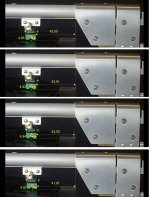
For those who have seen my "crash test" (sorry, a mistake in the specifications: the old disc used for this test has the hole enlarged to 8.5 mm, the eccentricity is therefore not + -1.5 m but 1.5 mm ca, (8.5 - 7.2 spindle =1.3 mm = max Riaa standard) and after the frames to avoid possible misunderstandings.
Now are carefully measured: as you can see, the carriage moves 1.18 mm, while the stylus bending is 0.13 mm, that still doesn't seem to me as "severe sideways flexing".
In his helpful post Niffy refers that only a > 0.20 mm bending is visible to the naked eye (this explains the "no visible bending" in my review) responsible of + -1° bias. Imho a measure under the tolerances of the elastomer and assembly of the cartridge, even for those manufacturers with highly sophisticated machines (just the largest ones).
Fully agree for the advantages of the weight of the carriage in relation to the resonances, despite greater friction (unfortunately unusable on mine): this applies to the normal situation of uniform motion, only when there is an acceleration (eccentricity) the mass comes into play, even if you live on the Skylab. The same can be said of the excessive vert. mass on Lil Casey, pleasantly sounding with LPs without steep warps.
The bearings of a tonearm have several important criteria to fulfill.
Having no torque on carriage allows the use of the simple 4 balls bearing: so more sensible than the bubble level that leveling the rail became a nightmare...
carlo
sorry I missed the posts of the last two pages...
Attachments
Last edited:
Hello super10018,
It is not my intention to put you or anyone else on the defensive. You are right when you say that it does not matter what I think because at the end of the day, you have designed and built a very nice tone arm.
Now, about the above quote, The tangential tone arm I have introduced in this forum a little while ago, fits the above description. The floating head-shell is driven purely by the grooves in the record. It is not driven by the tone arm's servo and therefore belongs in this thread. 🙂
Sincerely,
Ralf
Ralf,
In fact, when I answered Ray’s post, I thought your arm immediately.
For a regular pivot arm, the changes of position of cartridge and tracking angle are driven by the force generated by groove wall only. I think we all agree it is a passive arm. There is no external force.
For Rabco tonearm, the changes of position of cartridge is driven by electronic powered force, i.e. a motor. It has slight changes of tracking angle, too. The changes of tracking angle are driven by the force generated by groove wall as well as the position of motor. Usually, an active arm has two parts, driving mechanism and feedback mechanism. Here, the change of tracking angle is a feedback mechanism as well. There IS an external force which is generated by power. We all agree it is an active arm.
For your arm, the position of cartridge is driven by the force generated by groove wall. But the changes of tacking angles are driven by electronic powered force. It is external force. Therefore, I will say your arm is an active arm. Correct me if I misunderstand the operation of your arm.
For air bearing arm, the cartridge will not move without the force generated by groove wall. Motor is NOT driving the bearing. The changes of cartridge position and tracking angle are driven by the force generated by groove wall only. There is NO external force to drive the cartridge. Compressed air functions same as the ball bearings on a mechanical linear arm. Therefore, it is a passive arm.
It really doesn't matter too much Whether or not an arm belongs in this thread as long as you feel the need to mention different kind of arm. I don't see anything wrong with that.
Jim
Last edited:
Air bearings are as active as oil-lubricated bearings. Same kind of role, but more luxurious.
my 0.2 cents - ciao carlo
my 0.2 cents - ciao carlo
Niffy, thank you, of course, it helps. In my own project of linear arm, the horizontal effective mass will be several times more, than vertical. It will be a hybrid of pivot Dynavector-like and a true linear arm. Frankenstein of linear arms, for fun of DYI. I hope, it will work well.
Air bearings are as active as oil-lubricated bearings. Same kind of role, but more luxurious.
my 0.2 cents - ciao carlo
It depends on how you define the word, active.
Niffy, I would like an explanation: in the comparison of Tracking Error # 2528 there is something that does not convince me.
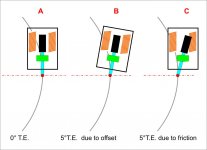
When the T. E. derives from the offset, the cantilever (and magnets) is aligned to the coils: there is only some rotation of the tip with respect to the tangent (in fact someone claims to hear it more on ellipticals than on conical).
When T.E. derives from friction (or skating) there is bending, so a magnet is closer than the other to his coil = different level between channels + distortion.
Am I wrong?
thanks - carlo
that said, hooray for bending, because without a bit the arms would not move, and goodbye music
Hi Carlo,
The graphs in #2528 show only the tracking error. Tracking error is the amount that the stylus is misaligned with the groove.
Some of the factors used only effect stylus alignment such as geometry, bearing play and the groove angle.
A couple of posts previous I posted this. "Tracking error due to bearing friction doesn't just cause the stylus to be misaligned with the groove but also to misaligns the generator in the cartridge. With small alignment errors this isn't much of a problem but with larger errors the coils/magnet can move out of the gap making the cartridge nonlinear with high levels of distortion."
Several factors effect both stylus alignment and generator alignment. These are bearing friction, skating and carriage enertia. Cartridges generators are linear for a range either side of their central/neutral position. Small misalignments of the generator stay within the linear range so have little effect on sound quantity. Larger misalignments move the generator out of its linear range resulting in distortion and lower sound quality.
The investigation into tracking errors was quite comprehensive. The graphs I used were selected as they are the most informative and easiest to follow of the ones I happened to have stored on my phone.
Niffy
I should probably add a bit to my previous post.
In the second graph in post #2528 that shows maximum tracking error the linear arm with standard grade bearings will almost certainly have its generator well outside of the linear range. Even the linear arm with high grade bearings is probability out of the linear range quite often. It is worth noting that the eccentricity of the record in this example is quite severe so on most records the effects of enertia will be less but the effect of friction will be about the same.
When adding all the different aspects that cause tracking errors you can't just work out each then add them together. Aspects like enertia and friction have their maximums at 90° of record rotation compared to the maximum of groove angle. The errors over a full revolution have to be summed.
Niffy
Thanks Niffy, what you say is right and thorough, but I still do not understand why to compare two situations that, even with the same angle of tracking error, have so different consequences. Maybe it's because here in Italy we simply call B errore di tracciamento (tracking error) and C flessione dello stilo (stylus bending).
Anyway congratulations, the analysis is really interesting: while that of the pivoted is well known from the null points calculation, I had never seen before that for the linear trackers. The bending considered is only that due to eccentricity or even the small one deriving from the friction of the carriage during uniform motion?
carlo
Attachments
Hi Carlo,
Great discriptive diagrams. I personally don't like the term "stylus bending" as it conjures the image of the cantilever physically being bent. I prefer generator misalignment though this does take longer to type. In your diagrams case B result in just tracking error. In case C tracking error and generator misalignment occur simultaneously and to the same degree.
In my previous investigation I looked at just tracking error. Now I'll look at just generator misalignment (GM) , unfortunately I don't have the graphs for this to hand.
GM is caused by bearing friction, the mass/inertia effect and skating. Pivoted arms suffer from the mass/inertia effect in the same way that linear arms do but to a lesser degree as their lateral mass is generally much lower. Of course linear arms don't suffer from skating force. Again I'll assume a record with a 0.5mm eccentricity causing a 1mm "wobble"
If these three effects are combined the total GM for a 9"pivoted arm would be slightly less than that for my arm with the jewelled bearings and slightly more than for the air bearing arm. These three arms with the eccentric record would have GM in the range of 0.2-0.3°, within the linear range of a good cartridge. (The two arms with ball race bearings would be considerably worse than the three arms above. The 12" would be slightly better than the 9")
If played on a perfectly centred record the main difference will be the elimination of the mass/inertia effect. The 9" arm would only improve by a very small amount, 0.02°. My arm would improve by about 0.07° dropping to around 0.23°. The air bearing would have virtually no GM at all.
The air bearing arm I modeled was much lower mass than Jim's design. It was, however, using a much higher compliance cartridge than the ones Jim uses. Because of this Jim's arm will probably have very similar performance to the modelled arm.
The three arms are quite close and all have low misalignments. The pivoted arm has still got the much higher lateral tracking errors.
Niffy
If these three effects are combined the total GM for a 9"pivoted arm would be slightly less than that for my arm with the jewelled bearings and slightly more than for the air bearing arm. These three arms with the eccentric record would have GM in the range of 0.2-0.3°, within the linear range of a good cartridge. (The two arms with ball race bearings would be considerably worse than the three arms above. The 12" would be slightly better than the 9")
Niffy
Niffy,
That is excellent analysis. It matches my expectations. Actually, I am building another perhaps my last air bearing arm. This one will use 3/4" bearing and total mass may be around 80 grams. This one will be the lightest one among my arms. I will fit an A90 cartridge for this arm.
Jim
Last edited:
ahh. OK.This is an advantage. A shorter arm will create less torque about the bearings. A shorter arm will also be more rigid. However making the arm too short can cause problems with increased VTA error (due to warps and varying record thickness) and increased warp wow. It's all a balancing act.
Niffy
If only we could move the whole contraption vertically just like typical pivoted tonearm ? I think a parallelogram type of assembly where rails (on which pulleys run) would be on one side and counterweight on other. Probably would be complex. And with more friction too.
Thanks and regards.
- Home
- Source & Line
- Analogue Source
- DIY linear tonearm