Niffy,
I often thought about the notion that lateral movement is limited, and horizontal locked in,this I agree is good with the two rail design. Also using only one set of bearings for both horizontal and lateral movement eliminates a couple sets of resonances along with firmer mechanical grounding. Having a higher lateral mass is not a bad thing, and this design allows it to be changed with different counterweights.
Colin
"I think the two rail version (thanks PDR) is probably superior to running inside of a tube as movement other than lateral is prohibited. It would be much easier to twist the carriage laterally as the bearings can slide up the inside of the tube different amounts. As the load inevitably has a torsional element this is likely to occur. With the 2 rod design it cannot."
would you be kind enough to further explain how you figure what you said works as I just don't see it. Thanks for the help. Best regards Moray James.
would you be kind enough to further explain how you figure what you said works as I just don't see it. Thanks for the help. Best regards Moray James.
Hi Morton.
Revisiting Supers diagram I note that he is using 15mm external tube. Assuming it has an inside diameter of 10mm and he is using 4mm wide bearings he would still have a contact angle of 20degrees so probably no difference to 2rod design. My original statement is probably invalid. I still prefer the 2 rod design as rigid support and the addition of damping material is nice and simple.
Niffy
Thanks Niffty I appreciate your reply. single tubes can be damped with adhesive lined shrink tube. A single tube also allows you to get the bearing pivot closer to the record surface than with parallel tubes but that aside they amount to the same thing more or less. a flat plate with a machined "V" grove would get it even closer. the twin tube would allow damping material to be packed into the tubes. rods (solid) would be harder to damp can you say what you were think of damping them with? best regards Moray James.
Hi Moray.
If using tubes they could be filled with silicone sealant. I'm using solid 4mm rods, separated by a 1.5mm carbon batten, mounted on a 3mm thick stainless steel bar with two 6mm thick walled stainless steel tubes either side of the glass rods. The tubes are filled with low modulus silicone. The whole assembly is glued together with epoxy. The resultant structure is very rigid and inert. With the stylus resting on a non-rotating record I can tap the rail assembly quite hard with a pencil and hear nothing through the speakers at normal levels.
One advantage of running inside a tube is that it is impossible to inadvertently derail the carriage. I have the same advantage as my rail passes through my carriage with less than a mm of clearance all round.
Niffy
Re:Where was my brain,
Replace lateral with vertical and keep horizontal as the same and or lateral and it makes sense, I'll blame the heat wave for the glitch 🙂.
Did some playing around with counterweights again just for fun, changes in vtf with a low slung counterweight are moot, in fact in beneficial from a tracking standpoint. There has been debate over this aspect, and this is where Bo Hanson really has something, and most arms today come with the option of and or with low slung weights that perform the same damping trick. As far as I gather on this subject the increase in vtf on the up of a warp helps damp the downward motion of the arm.
Colin
As long as the variation in tracking force remains within the cartridges tracking force range I would agree. Excessive variation in tracking force will lead to the cartridges generator being misaligned which will have a negative effect. Also, due to warps, the stylus will be misaligned verticaly in the groove due to the slope of the records surface. Excessive tracking force will deflect the cantilever worsening the effect.
Niffy
Niffy
Hi Niffy,
The glass tubing I ordered is 16mm OD, 11mm ID and 2.5mm wall. My bearing is 4x9x4mm. It should fit inside of tubing perfectly. I don’t have the glass tubings yet. I tried to fit the bearing in a 10mm ID tubing, it works fine as well.
In fact, I think it is more stable to run inside of tubing than to run on two tubings. One thing I don’t understand is why Clear Audio uses convex bearings because convex bearings allow more lateral movements. They must know something that We don’t know. Anyway, in my 2nd arm, the glass rails can be easily change to twin tubings or one C shape tubing without modifying anything else. I will try both.
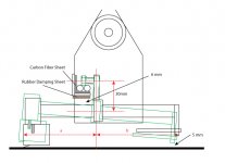
With regard to 30mm on the “T”, it is almost the smallest size I can do. Please see the drawing.
From my experience, a shorter distance A (see drawing) may be better. But it can’t be too short. If it is too short, the arm won’t be stable. The distance A should be almost same as distance B in order to maintain stability of arm.
Jim
The glass tubing I ordered is 16mm OD, 11mm ID and 2.5mm wall. My bearing is 4x9x4mm. It should fit inside of tubing perfectly. I don’t have the glass tubings yet. I tried to fit the bearing in a 10mm ID tubing, it works fine as well.
In fact, I think it is more stable to run inside of tubing than to run on two tubings. One thing I don’t understand is why Clear Audio uses convex bearings because convex bearings allow more lateral movements. They must know something that We don’t know. Anyway, in my 2nd arm, the glass rails can be easily change to twin tubings or one C shape tubing without modifying anything else. I will try both.
With regard to 30mm on the “T”, it is almost the smallest size I can do. Please see the drawing.
From my experience, a shorter distance A (see drawing) may be better. But it can’t be too short. If it is too short, the arm won’t be stable. The distance A should be almost same as distance B in order to maintain stability of arm.
Jim
Attachments
Hi Super.
Keeping distances a and b similar definitely can help. Making b the wrong length can do nasty things to the effective mass. Have you done any calculations to determine what it will be? I've been designing a lighter carriage for my arm just to see how it compares to my current model. A simple spread sheet allows me to evaluate how the design effects carriage mass, tracking force, effective mass and vertical location of COM. Balancing all these factors is crucial.
Looking back at the photos you posted I can see that reducing the hight of the T section might prove difficult without bringing the bottom of the support structure too close to the record surface.
I notice that you have gone with a Colin style head shell in your drawing. I'll be interested to hear how it works for you. I've opted for a half hight version as I couldn't get a good balance of factors with the square version (as I'm designing the carriage to fit my base my design criteria are different than yours).
I love your ring clamp. It definitely follows my design philosophy, give the job of dealing with warps to the deck not the arm. In fact as it removes a major burden from the arm it could be seen to be as much a part of the arm as it is of the deck so it's discussion here is definitely not off topic. Would you mind sharing a bit about it. How did you make it and did you balance it.
Niffy
Hi super10018
Bearings with a convex outer race find center at the inside bottom of the tube by virtue of gravity. When the tone arm encounters a warp, the bearings roll back and forth on the bottom of the tube, hence rolling friction, the most desirable kind. Make a simple sketch of the Clear Audio design, looking at it from the end of the tube, and you will know what Clear Audio knows. 🙂
Sincerely,
Ralf
One thing I don’t understand is why Clear Audio uses convex bearings because convex bearings allow more lateral movements. They must know something that We don’t know.
Bearings with a convex outer race find center at the inside bottom of the tube by virtue of gravity. When the tone arm encounters a warp, the bearings roll back and forth on the bottom of the tube, hence rolling friction, the most desirable kind. Make a simple sketch of the Clear Audio design, looking at it from the end of the tube, and you will know what Clear Audio knows. 🙂
Sincerely,
Ralf
Ralf,
Wouldn't it be fairer to give credit to Bo, to me and what ive gathered Clearaudio has some questionable business practices on intellectual property🙂.
Colin
Wouldn't it be fairer to give credit to Bo, to me and what ive gathered Clearaudio has some questionable business practices on intellectual property🙂.
Colin
Last edited:
Bearings with a convex outer race find center at the inside bottom of the tube by virtue of gravity. When the tone arm encounters a warp, the bearings roll back and forth on the bottom of the tube, hence rolling friction, the most desirable kind. Make a simple sketch of the Clear Audio design, looking at it from the end of the tube, and you will know what Clear Audio knows. 🙂
Sincerely,
Ralf
Bo explained to me that clear audio got it wrong with regard to the bearing profile they used but they did it for a reason all be it a poor one they did not do it for performance as Bo had already proved that the flat bottom bearings with four points of contact worked better. Bo's original bearing functioned the same way though different in appearance to the clear audio. This is just one of the non obvious design features that Bo conceived.
Bo's original design bearing had a small narrow flange upon which the carriage could rock back and forth just as with the clear audio bearing. Now while this does allow the arm assembly to more easily track severe warps it becomes a point of physical resonance and a results in a physical loss of energy transfer at the cartridge. Don't miss this very clever and important design aspect in Bo's design. Arm motion is accounted for under normal flat record play via slack in the bearing race assembly and when larger than normal record surface variations (warps) are encountered the assembly is forced to take to the wall of the glass tube and rid up so that the cartridge can navigate the warp. Gravity then pulls the bearing assembly back down to where it belongs as soon as the warp has been passed. The friction involved in the bearing assembly being dragged up the wall of the glass tube damps the system during this motion. This is not the case in Bo's original version of the design or in clear audio's copy. I hope that this helps. Best regards Moray James.
PS: I agree that a central record clamp and also peripheral record clamps are very good ideas. As Bo said many times to me you don't play warped records they sound bad buy a flat copy of the disk. Just because Bo's original arm design could play horrendous warps it did not make them sound any good. The new design can still play a large warp (but not near so large as the original design) but the real bonus is that the new design sounds better on any record as a result of the increase stiffness of the system.
Ralf,
I understand what you are saying. Personally, I am not fond of so called knife edge effect theory.
One of benefits to use convex bearing is VTF is a constant force.
In order to avoid lateral movements, the down force generated by arm moving mass must be stronger than the pulling force caused by friction between stylus and record groove. In reality, the irregularity of record surface may knock convex bearing off center. Therefore, the weight of moving mass is very critical. I guess Clear Audio might find the right balance between pulling force and down force. Optimal down force will keep convex bearing centered inside of glass tubing. 43 grams may be a good reference point for arm moving mass in stead of 20 something grams.
Attachments

Ralf,
I understand what you are saying. Personally, I am not fond of so called knife edge effect theory.
One of benefits to use convex bearing is VTF is a constant force.
In order to avoid lateral movements, the down force generated by arm moving mass must be stronger than the pulling force caused by friction between stylus and record groove. In reality, the irregularity of record surface may knock convex bearing off center. Therefore, the weight of moving mass is very critical. I guess Clear Audio might find the right balance between pulling force and down force. Optimal down force will keep convex bearing centered inside of glass tubing. 43 grams may be a good reference point for arm moving mass in stead of 20 something grams.
Take a good look at the drawing. The glass tube is the outer race of a bearing. The convex race is the inner race of that bearing. Same thing as what is going on inside that very convex outer race bearing. How many times are you going to put these elements in series? How many of Bo's resonant pointe are you going to establish to the detriment of all? IMHO the only design that makes any sense at all is the 4 tube 2 ball design.
BillG
Niffy,
No. I have not done any calculations so far. If you have a simple spread sheet and it doesn’t cause you too much trouble, I would love to see it.
Yes. I am going to do same kind of head shell as Colin’s. I also took your advice to drill two larger holes for adjusting zenith. The head shell will be a solid block of aluminum.
I will take some pictures to show the construction of outer ring.
Hi Colin
It was not my intent to take away credit from you, Bo or anyone else involved in tone arm design. You are all to be complimented.
My comment was strictly meant to apply to the technical reasons behind their version of that design.
At one of the C.E.S. Shows I saw Clear Audio tone arms using Frank Schroeder's string suspension while he had a patent on that design.
Sincerely,
Ralf
Ralf,
Wouldn't it be fairer to give credit to Bo, to me and what ive gathered Clearaudio has some questionable business practices on intellectual property🙂.
Colin
It was not my intent to take away credit from you, Bo or anyone else involved in tone arm design. You are all to be complimented.
My comment was strictly meant to apply to the technical reasons behind their version of that design.
At one of the C.E.S. Shows I saw Clear Audio tone arms using Frank Schroeder's string suspension while he had a patent on that design.
Sincerely,
Ralf
With a convex outer race bearings running inside of a glass tube the point I made at the bottom of post 1840 is valid. Not only will the bearings be pulled slightly forward of the bottom of the tube a different amount depending on stylus drag they will also be pulled up a different amount due the lateral torsion created by bearing friction.
Niffy
Niffy
When the bearing moves up/down into the tube, there is dry scrapping.
So, there is hysteresis and the bearing can't return at the initial place.
Am I wrong ?
So, there is hysteresis and the bearing can't return at the initial place.
Am I wrong ?
Bill,
The 4 tube 2 ball is a neat design but honestly doesn't lend itself to a commercial product very well. I use a two tube two bearing version and I could be outside the house and still tell that the sonics knock the socks off of any digital source I have heard on a good pressing. But as has been demonstrated that these designs with bearings and or air lend themselves to a user friendly product. I think only us diy would have any interest in fiddling with balls beyond the regular setup 🙂.
Colin
I like two balls idea as well. If I do, I will do the following.
1. Don’t use 90 degree angles as rail. I will use 120 degree angles and glue glass bars on the contact sides of rails.
2. Use two ceramic balls. Not steel balls.
1. Don’t use 90 degree angles as rail. I will use 120 degree angles and glue glass bars on the contact sides of rails.
2. Use two ceramic balls. Not steel balls.
- Home
- Source & Line
- Analogue Source
- DIY linear tonearm