@Mike56 the anomaly at 160Hz is about 0.5dB which could be environmental, I would not spend time chasing it at this point.
The plot looks pretty good and is approx +0.5dB / -1.2dB until 16kHz.
With the resistive load testing I would start with a load of 10kR and work up. 13kR in parallel with 47kR will give you close to 10kR. Keep in mind lowering the resistive load will drop the level of the whole plot. I would use a 1kHz tone to normalise levels between different loads before you run the pots.
Useful thoughts Warrjon, what is the zero point when you say +/- please
To normalise levels, do i go somewhere in REW or on the computer please?
M
To normalise levels, do i go somewhere in REW or on the computer please?
M
Afternoon All,
I put a 47K resistor in parallel across both100 and 220pf capacitance levels and measured both, i haven't bothered to plot them as they are both falling 5 or 6 Db between 1000 Hz and 10,000Hz, suggesting this is going the wrong way already, so without knowing how i might increase the resistive load, i shall put this area on pause for now. maybe one day i will re-package the input area of the phono pre with its own little input load switchable choices going also above the 47K resistive load.......?
M

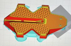
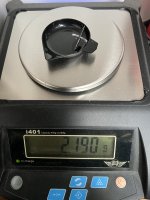
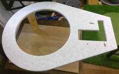
Wheels are now complete, total weight per wheel/axle = 2.180g very pleased with this weight saving. Having a go at proofing the carriage with two different infill densities and patterns. Triangles at a higher density which should give higher compressive strength at the cartridge mounting holes and cubic throughout the rest which should give some nice triangulated forms within.
Wheels/axles 4.36g
Sapphire vees and mounts 2.59g
Cartridge 7.2g
Carriage 26g
Total before CW and ballast = 40.15g
That leaves me with 15.85g to play with for CW and ballast.
Hopefully going to hear something soon!
S.
Wheels/axles 4.36g
Sapphire vees and mounts 2.59g
Cartridge 7.2g
Carriage 26g
Total before CW and ballast = 40.15g
That leaves me with 15.85g to play with for CW and ballast.
Hopefully going to hear something soon!
S.
Attachments
Looking forward to hearing what you hear!
Whilst my diversion onto cartridge loading, caused by measuring frequency response is not complete, i hope at some stage to return to the evolution of my RTA.
When you've completed your first, you might make a comparison..............!?
Whilst my diversion onto cartridge loading, caused by measuring frequency response is not complete, i hope at some stage to return to the evolution of my RTA.
When you've completed your first, you might make a comparison..............!?
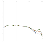
OK, so I removed all external resistors so R remains at 47k
I only have the two pairs of capacitors so added 100 plus 220 = 320pf
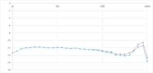
A logical progress is demonstrated as per attached graph…….
Lowest in treble area grey is 0pf
Next up blue is 100 pf
Next up red is 220 pf
Next up funny murky dark green colour! Is 320pf
Nothing wrong with the shape up to say 10kHz as I see it, it would be nice to spread the trough and peak right and smooth it, which I read would happen with increased resistance across the inputs, but I have to go into the amp to do that…..
The 160 Hz trough is quite an unstable reading, some resonance or vibration artefact?
I only have the two pairs of capacitors so added 100 plus 220 = 320pf
A logical progress is demonstrated as per attached graph…….
Lowest in treble area grey is 0pf
Next up blue is 100 pf
Next up red is 220 pf
Next up funny murky dark green colour! Is 320pf
Nothing wrong with the shape up to say 10kHz as I see it, it would be nice to spread the trough and peak right and smooth it, which I read would happen with increased resistance across the inputs, but I have to go into the amp to do that…..
The 160 Hz trough is quite an unstable reading, some resonance or vibration artefact?
Attachments
Now I know why it is useful to be able to plot a frequency response!!!!!!
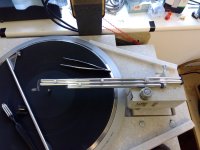
Soon after changing the capacitance, I was taking a look at the various parts of the RTA, applying test/check lumps of blue tack and found the 160 Hz anomaly in about 10 minutes!
I have now coated the lift arm in black tape, the heat shrink I was going to use was just too tight but that would probably be an incremental improvement for the future.
I have now replotted the curve because it was obvious it now stays flat straight through the 160Hz point. So below 1000Hz the curve is within 1dB now. i did not record above 1000Hz but there were small improvements throughout that as well, shows how one thing can affect others.........
I am sure it is imagination, but the piano sounds much more piano-like now!
M
Attachments

Hi all,
I somehow have managed to not get any post notifications for quite a while.
Looks like a lot interesting stuff has been happening.
Sether,
those wheels look absolutely gorgeous. The profile of the axles is super clean. I'm very much looking forward to hearing your impressions of how they effect the sound.
Also great to see an adaptation of my carriage design. Does your CAD have FEA and have you been able to calculate the expected resonant response?
My counterweight is flat plate of 4mm stainless steel. It is 18mm wide, 21mm long and sits within a shallow recess in the bottom of the carriage. This prevents the weight from moving or twisting as the locking bolt is tightened. The rear of the carriage has a groove to allow access to the locking bolt from above. The counterweight weights 11g. Having this steel plate tightly bolted up against the bottom of the cartridge actually adds quite a bit of rigidity to the carriage as its entire upper surface is in intimate contact. It also helps to prevent the weight and rear of the carriage from resonating.
The bottom of the weight is about 2.5mm above the surface of record so helps to keep the COG as low as possible.
It would have been nice if I had incorporated some form of screw adjustment for fine tuning tracking force as this can be a little bit tricky though it isn't all that hard to do. Once set the weight isn't going to shift as it's basically part of the carriage body.
Niffy
Thanks niffy, I’ll look into the FEA. I’ve proofed one carriage and it needs some tweaking. I was a little tight on the tolerance where the rail passes through. It’s funny how things look massive in the CAD program but in reality it’s tiny. I took the chance to experiment with heat treating the print by baking in the oven at 90degC as I’ve heard that this can increase strength in the PLA. It certainly helps but it introduces more dimensional inaccuracies with uncontrollable thermal distortion. Thanks for the info on the CW I was wondering how you did it.
I’m thinking about the plinth for my 401. I know there are some interesting threads about this but they mostly relate to pivot tonearms on a tonearm boards and inevitably lead to densified wood. It would be interesting to see what you Gents have implemented. Am I best to have the gantry on the same board as the 401? This offers the stiffest connection but might introduce motor vibration into the gantry.
S.
Hi Sether --PLA - Try a bath in diluted white glue, or even better, epoxy - was higly beneficial for the strength of the parts of my 3DToy PTTA (and maybe less risky than the oven = possible distortions) - As said the resonnces behavior didn't convince me, too damping for may taste
carlo
carlo
Thanks Carlo, I’ll give it a try. Really the idea of the print is to test the concept, once satisfied I’ll invert the print and mould a composite version. Maybe with a PLA plug and a CF skin.
Has anyone used Paxolin phenolic paper sheet for plinths? Contains the magic‘phenolic’ resin, beloved by densified wood advocates. Probably has different damping properties though. @Mike56 i see that you use a Corian type material for your plinth, is your arm mounted on the same panel as your turntable or on a separate piece?
S.
Hi Sether, Used as a plug seems a really good idea, presumably you could also cut the mould direct?
Cats Squirrel on https://www.diyaudio.com/community/threads/diy-cld-plinth-design-a-measured-approach.312473/latest
could be your helper here.
I believe in the Spindle being coupled to the arm, so they vibrate as near identically as possible, and of course as little as possible.
I measured improvements when i did that.
So my arm is mounted on the same base as the TT, its got a hole for the TT and a hole for the arm, an extension of the same thing to allow easy level and height adjustment. here is a pic both as cut and during assembly.
I had read that Corian type materials could be good and had some, i also read about true CLD. i don't believe my use of either Corian or CLD are good solutions, its an area i can seek improvements, but i am reluctant to spend what Panzerholz or similar would cost, so seek a magic simple DIY solution!
Attachments
Thanks for the link Mike, I’ll see if there is any info on that thread about phenolic paper boards. A lot more affordable, £25 per sheet at my local electrical shop. I even think toolstation stock it (UK). I agree, there must be an affordable DIY approach to plinth building. After all Permali and the like, were not conceived to be damping panels it’s just lucky for the audio community that they do possess intrinsic damping properties.
S.
S.
Densified wood is a dense unidirectional fibre reinforced composite.
Maybe another fibre reinforced composite would make a good plinth, glass, carbon, Kevlar, i expect they have all been tried?
Maybe another fibre reinforced composite would make a good plinth, glass, carbon, Kevlar, i expect they have all been tried?
Many years ago I helped out with a 401 build, it was a totally bonkers project.
We cut out lots of pieces of lead sheet and siliconed them into the spaces between the webs on the underside of the 401. The plinth was a large welded 6mm steel box that was lined with 18mm ply. The box was then filled with layers of varying density materials starting with lead-shot loaded cement working down to plaster of Paris. The layers were all sculpted to create a very organic form for the internal space into which the 401 sat. The whole thing was totally inert.
The platter was topped with a 20mm thick slab of pure graphite. I believe it was from a Nottingham Analogue deck.
I don't recall what arm was used.
The whole thing weighed in at about 100kg. It is one of the best decks I have ever heard. I believe that he still has it somewhere but it's not currently in use.
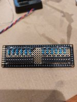
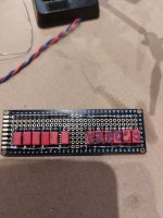
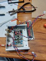
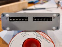
Going back to when i minimalised the output wiring i have now completed my project to incorporate an input loading adjustment in my phono pre.
Various contributors gave me help, support and encouragement, many thanks.
Whilst initially it seemed easy enough i learnt a couple of things en route.
Spare space in the case is useful, it ended up a bit tight to fit!
Prototype breadboards with lands you can bridge with solder don't work for me, the gap to bridge is tiny, but try as i might i could not achieve a bridge so ended up wire bridging all the connections, which is not tidy.
However, that aside, here is a picture of the construction and two DIP switches in the case, this gives me six capacitance and six resistance options on each channel, - an almost infinite number of combinations, but only a few relevant to each cartridge.
Having now run the experiments i can get 20-16,000Hz at less than 3dB variation in a couple of ways, but its clear, from what i can see, my Technics 205 likes to see 220pf plus whatever is in the cables and 85-100kOhm resistance.
Attachments
And happy to say i believe the sound is better, clearer vocals etc.
Which allows me to revert to the subject of the thread, it allows my RTA to sound better!
More to the point i hope to use the new (to me) measurement technique to search further improvements, i found one vibration en rote already.
Which allows me to revert to the subject of the thread, it allows my RTA to sound better!
More to the point i hope to use the new (to me) measurement technique to search further improvements, i found one vibration en rote already.
Is your TT already mounted? - if so i suggest mount the TA and test it before making anything new, then you can incorporate the things you learnt when you build a new plinth. contributors on the thread always encouraged me to modify only one thing at at time, and its valid advice! - then you're more likely to know what has caused changes, good or bad.Thanks for the link Mike, I’ll see if there is any info on that thread about phenolic paper boards. A lot more affordable, £25 per sheet at my local electrical shop. I even think toolstation stock it (UK). I agree, there must be an affordable DIY approach to plinth building. After all Permali and the like, were not conceived to be damping panels it’s just lucky for the audio community that they do possess intrinsic damping properties.
S.
- Home
- Source & Line
- Analogue Source
- DIY linear tonearm