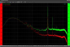
Mike. That reduction in sidebands indicates that you have removed some of the toner resonances.. Well done. The 40Hz issue has to be related to the turntable.. it went away when turning at 45RPM.. do you know the RPM of the driver motor? Forgive me.. Is this a belt or direct drive system?
Mike. That reduction in sidebands indicates that you have removed some of the toner resonances.. Well done. The 40Hz issue has to be related to the turntable.. it went away when turning at 45RPM.. do you know the RPM of the driver motor? Forgive me.. Is this a belt or direct drive system?
Hi there and thanks, i was puzzled by that result i thought it would go up in frequency with the motor if that was the case?
i dont know the motor revs but i measured its spindle as 8.5mm diameter and the platter at 295 ish, says the motor must be 1156rpm?
the TT is Origin Live Aurora IV, i can detect no noise from it in my measurements by any method I've worked out so far.
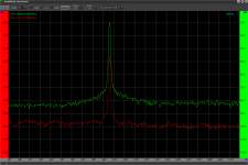
Here attached is screen shot 255 with the styus on a stationary record and the belt off, then 266 when i switch on the motor, gives me that 20hz, but not 40 and this on massive zoom, but maybe there is something in it?
Attachments

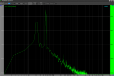
We may be upon something... The belt may be providing some sort of mechanical rectification resulting in the frequency doubling from the 20Hz to 40Hz. Have you tried changing the belt tension? It may be that at 45rpm, there is no belt resonance or it is distributed enough to damp out the effect. That could be why it was not seen at 45RPM.
Thanks for those thoughts, i shall have a good study tomorrow and update you
Unfortunately i have found no progress on the 40Hz, yet. the only thing i established is that it is also present when i mount the same cartridge in my conventional pivoted arm, everything else remaining the same, so it is something TT/mounting related. I shall continue to seek it out.
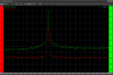
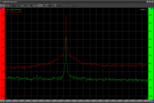
Meanwhile i have worked hard on set up and azimuth adjustment and achieved the attached outputs showing crosstalk from the tone on each channel. It seems very similar, minimum sidebands etc - how does this look in absolute terms?
Mike
Attachments
Unfortunately i have found no progress on the 40Hz, yet. the only thing i established is that it is also present when i mount the same cartridge in my conventional pivoted arm, everything else remaining the same, so it is something TT/mounting related. I shall continue to seek it out.
Mike
So writing the note above prompted me to do some experiments.
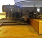
I think a lot is about how i have the motor mounted, i thought it was pretty good on a split beech block plinth on a damped wall shelf.
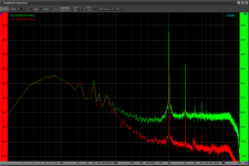
However, with the belt off, and the stylus on the stationary record simply running the motor showed up some 20 and 40 Hz energy.
The before plots are SS 325 and SS328
After experiments the motor is now sat on a tatty pile of MLV (mass loaded vinyl)
I have the results shown in SS338 and SS 341.
Audibly the low frequency background noise is reduced a touch.
Many thanks for those who persuaded me to understand enough to start measuring things with a ADC and VA, its been very revealing and interesting.
M
Attachments

Many thanks for those who persuaded me to understand enough to start measuring things with a ADC and VA, its been very revealing and interesting.
M
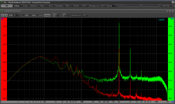
Folks, i have kept experimenting with this area and achieved only a little progress that you can see in the attached plot.
I would value feedback on whether this looks good, bad or average and any hints about the possible improvements i might seek. Noise floor reductions improve the sound for me a lot so any ideas there also most welcome.
Mike
Attachments
Hi Mike,
If I were you, I wouldn't worry about 40 Hz. The critical issue here is to find your arm/cartridge resonant frequency. If the arm/cartridge resonant frequency is above 20 Hz, it is problematic. Otherwise, you are fine.
Jim
If I were you, I wouldn't worry about 40 Hz. The critical issue here is to find your arm/cartridge resonant frequency. If the arm/cartridge resonant frequency is above 20 Hz, it is problematic. Otherwise, you are fine.
Jim
Hi Mike,
If I were you, I wouldn't worry about 40 Hz. The critical issue here is to find your arm/cartridge resonant frequency. If the arm/cartridge resonant frequency is above 20 Hz, it is problematic. Otherwise, you are fine.
Jim
Thanks for that input Jim, its very useful.
I have considered carefully how to calculate the resonant frequency and been stumped by the theory.
The traditional formula for pivoted arms considers the mass and lengths either side of the pivot, often treating horizontal and vertical the same, and to my knowledge always treating the pivot as the end of the resonant entity.
The reason i mention the pivot is that when considering my arm the first of its pivots is just 15mm from the stylus in the horizontal plane and 20mm in the vertical and that distance is made up of pieces that don't fit the normal theory.
Now for my arm the relevant vertical movement is perhaps the three mobile pieces of the parallelogram, or perhaps only one. either way, they are all light, short and stiff and maybe as others have suggested the resonant frequency is very high. The horizontal mass may be the whole moving cart, but how to calculate anything i have no idea.
I have played the old resonance sweep on a test record a few times and also identified nothing.
So i remain (happily?) ignorant of the resonant frequency (s) and would be most interested to know how to identify it or them!
Many thanks
Mike
Hi Mike,
It is almost impossible to calculate the resonant frequency due to the complexity of your arm. The parallelogram is a spring that adds difficulties to calculate the resonant frequency.
The best to do is to find a test lp, which has resonant frequency testing tracks, such as Hifi News Test LP. However, from your 1K plots, I suspect the resonant frequency may be above 20 Hz.
If the resonant frequency is above 20 Hz, I would suggest keeping the arm as long as you like the sound. From your 1K plots, it seems to me that channels are not balanced. You may try to improve that. If you want to improve the arm and to move the resonant frequency below 20 Hz, my suggestion would be to remove the mechanism of the parallelogram completely. In my opinion, the parallelogram is a very clever design, but it is not necessary at all. You lose more than you gain.
Jim
Last edited:
Thanks Jim so much for responding, i hope you will continue to offer me valuable input it is much appreciated.Hi Mike,
It is almost impossible to calculate the resonant frequency due to the complexity of your arm. The parallelogram is a spring that adds difficulties to calculate the resonant frequency.
Jim
I am interested to know how you see it as a spring, i see numerous other things about it but at small displacements it gives constant VTF in warp which suggests to me it is linear with some friction like other principles?
I have an old HFN disc which has a track sweep from 23 to 6 Hz, i have played it a few times and learnt nothing, is there a useful way i can record that to view something please?Hi Mike,
The best to do is to find a test lp, which has resonant frequency testing tracks, such as Hifi News Test LP. However, from your 1K plots, I suspect the resonant frequency may be above 20 Hz.
Jim
I completely accept what you say Jim, but i like the idea that it presents constant VTA in warp, does it matter, i don't know but i guess i am like many others, i would like to make this work as best it can.If the resonant frequency is above 20 Hz, I would suggest keeping the arm as long as you like the sound. From your 1K plots, it seems to me that channels are not balanced. You may try to improve that. If you want to improve the arm and to move the resonant frequency below 20 Hz, my suggestion would be to remove the mechanism of the parallelogram completely. In my opinion, the parallelogram is a very clever design, but it is not necessary at all. You lose more than you gain.
Jim
I like the idea that it is inexpensive and can be easily made with handtools, so for now i will persevere, however, you never know, one day!
At the moment as well, i do like the sound, I am not an expert in any way, have never heard the high end results some of you achieve etc.
What are you currently favouring Jim as the best result someone like me might seek please?
Thanks again, hope you might find time to feedback
Mike
Hello Mike. You've done a great job and made a tonarm that plays better than any turning tonearm. Don't look for what this tonearm doesn't have, listen to the music and enjoy it.
If you’re bored, you can work on how it looks.
If you’re bored, you can work on how it looks.
Hi Mike,
If you did a sweep from 6-23 Hz, you found nothing. It meant that the resonant frequency might be above 23 Hz.
If you place the cartridge directly under the rails, you need to deal with the warp and have to use a complex structure of parallelogram. My question for you is what are the advantages to place the cartridge directly under the rail. Personally, I don't see and will be happy to learn from anyone. If the arm wand is 3-4 cm long, or Niffy's style arm, warp should not be a problem at all. If I remember it correctly, he did a calculation regarding warp under the condition of a short arm. You don't need to deal with warp. And, the arm is much simpler. The simpler, the better for arm designs.
For mechanical linear arm, I highly recommend Niffy's arm. In my opinion, there are simply no mechanical linear arms better than his arm so far no matter DIY or commercial.
As I said before, if you like the sound of your current arm, you may just use it as long as you are happy with it.
Jim
Last edited:
Hi Mike,
If you did a sweep from 6-23 Hz, you found nothing. It meant that the resonant frequency might be above 23 Hz.
If you place the cartridge directly under the rails, you need to deal with the warp and have to use a complex structure of parallelogram. My question for you is what are the advantages to place the cartridge directly under the rail. Personally, I don't see and will be happy to learn from anyone. If the arm wand is 3-4 cm long, or Niffy's style arm, warp should not be a problem at all. If I remember it correctly, he did a calculation regarding warp under the condition of a short arm. You don't need to deal with warp. And, the arm is much simpler. The simpler, the better for arm designs.
For mechanical linear arm, I highly recommend Niffy's arm. In my opinion, there are simply no mechanical linear arms better than his arm so far no matter DIY or commercial.
As I said before, if you like the sound of your current arm, you may just use it as long as you are happy with it.
Jim
It is a matter of friction in the rails IMHO.
I once heard an analogy: If you want to push a car you dont use a 10 feet side pole to do that.
It has not so much to do with warp handeling.
Interesting thoughts Koldby and Jim.
I also thought the short arm solution might have had some limitations in applying torque to the cart on the rails and also in VTA variance in warp movement and stylus speed relative to the groove at the same time.
I didn't know if or how much this mattered and think the parallelogram movement is actually quite simple to execute and remove all these possibilities.
The radial rail means the arms are very short.
My guess is that the resonances of the two types would be quite similar.
The geometry i have means i could easily vary weights and lengths if i knew what i was trying to achieve (for vertical). i just split the CW leverage required over two arms rather than one, but that allows the orientation to stay constant. Horizontal is presumably the whole cart etc and perhaps a similar thing to the short arm situation........
Niffys arm requires a quite sophisticated mechanical workshop and a skilled builder to achieve his results and get sufficient low friction to overcome the torsion forces on the carriage that is the result of not having the cartridge directly under the rails.
And quite costly materials as well..
But still only IMHO
And quite costly materials as well..
But still only IMHO
It is a matter of friction in the rails IMHO.
I once heard an analogy: If you want to push a car you dont use a 10 feet side pole to do that.
It has not so much to do with warp handeling.
I don't know how much friction can be reduced by placing the cartridge under the rails. Let's assume it does reduce friction. But the total mass of a carriage would be increased as well due to the mass of the parallelogram.
Friction is everything for a linear arm. If we want to reduce the friction, we need to go directly to the rail construction. I am not fond of the current construction of Mike's arm either. 16 contact points and two inverted triangle channels as sub-rails have too much friction to start with not to mention the total masses of sub-rails and the parallelogram, etc.
I am sorry and don't mean to discourage the spirit of DIY. I merely want to express my opinions to improve our DIY projects for fun and learning.
Jim
Last edited:
Hi Jim, firstly, thanks for the replies, no apologies necessary for me, in fact the opposite, it is great that you and others contribute. I value input enormously, especially from those with knowledge and experience to be considered, but actually of any sort to promote some thinking and consideration. this encourages rather than discourages, and increases the fun and learning!I am sorry and don't mean to discourage the spirit of DIY. I merely want to express my opinions to improve our DIY projects for fun and learning.
Jim
At the moment my set-up has grown heavier than it was previously as i stiffened various parts to dispel the sidebands to a great extent.I don't know how much friction can be reduced by placing the cartridge under the rails. Let's assume it does reduce friction. But the total mass of a carriage would be increased as well due to the mass of the parallelogram.
Jim
Weights are as follows
Cart including the mobile rails and the fixed pivot plate attached to it 18g
Top lever plate of the parallelogram (including two counterweights of 2.5g each) total 9g
Front plate, cartridge carrier and cartridge (which is 7g) total of 18g
Bottom lever plate including its 2 CW's 11g
Add those 4 items up and we have 56gms in total
I did have it lighter but stopped aiming for that when i read (i think it was Niffy?) that he felt the sound was better at a slightly heavier weight.........
So i hope i have an acceptable weight and reduced friction by being radial rail, if that works that way, and the constant orientation due to the parallelogram motion.
Jim, i now have different rails, i posted in the last month or so, V on V front rails, two balls = 8 contact points there, plus flat on V subsidiary rail single ball (which removed the self adjusting suspension requirement, and was an idea i borrowed from a response), now only 3 points there, so a total of 11.Friction is everything for a linear arm. If we want to reduce the friction, we need to go directly to the rail construction. I am not fond of the current construction of Mike's arm either. 16 contact points and two inverted triangle channels as sub-rails have too much friction to start with not to mention the total masses of sub-rails and the parallelogram, etc.
Jim
I thought i had done really good work, should have been around 70% of previous friction, but i am not sure i could perceive or measure a difference when i did that.............which was disappointing.
I am sorry and don't mean to discourage the spirit of DIY. I merely want to express my opinions to improve our DIY projects for fun and learning.
Jim
Back to the beginning Jim, absolutely no apologies necessary, please go on with constructive criticism and input, you've done it in a nice way anyway!, i will try and take it, learn and improve what i am making my way with the great help of lots of you folk out there!!
Mike
- Home
- Source & Line
- Analogue Source
- DIY linear tonearm