Hi Jim,
I always loved the look of this early version of your arm. It looks more like part of something designed to detect gravitational waves than a tonearm. It has real laboratory chic.
Niffy
I always loved the look of this early version of your arm. It looks more like part of something designed to detect gravitational waves than a tonearm. It has real laboratory chic.
Niffy
Warrjon,
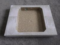
Please see the drawing. I meant that the bridge should be on the same platform as the bearing of the turntable. I expanded the platform on my turntable so the bridge is located on the same platform. In other words, it should be on the same platform as you normally mount your regular pivot arm.
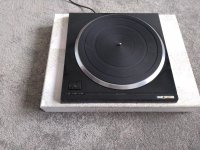
Warren will probably have a better knowledge of this than I do. It is my understanding that the technics SP10 doesn't have any inbuilt suspension. The top plate of the SP10 is solidly attached to the larger plinth to which the arm is mounted so is on the same platform as you recommend. I completely agree with you that the arm has to be mounted on the same platform as the bearing of the turntable.
Niffy
I see. After looking at his photo again, I realized that the table sits inside of the opening of the bottom plinth. So, I think it should be ok.
The SP10 is a motor only with no facility for mounting a tonearm and no suspension. The plinth this will be mounted in is 500x400x80mm resin/bentonite and very rigid and about 15kg. My suspension is between the TT plinth and the rack.
Attachments
Jim what did you make the arm rail mounting from? I like the way you have done this. The arm rail hangs lower from the mounting.
I notice you have used linear bearings for the vertical movement. I thought about doing this but instead decided to use a hard brass bush. Locking the vertical movement will be via a set screw from the rear of the upright.
I notice you have used linear bearings for the vertical movement. I thought about doing this but instead decided to use a hard brass bush. Locking the vertical movement will be via a set screw from the rear of the upright.
Fascinating analysis, Niffy. Saying to examine in the quality of the movement as well as the quantity, I really hoped that such observations #3356 would arise.
Mine date back to several years ago; with a 40 gr carriage on skf bearings the movements were what you describe so well. More - observing with the makroscope I saw that the carriage continued a little beyond the eccentricity.
Since observing that the friction was less than the stiction (guessing a 50% for those ball bearing) I thought that the turning point is not a real stop (it lasts time = 0) but a reversal of motion. Therefore there's no real stiction, just the inertia pushing the mass of the carriage in friction mode, held back by the stylus into the groove
Now however, your calculations convinced me too that the inertia is too small to justify such behavior. Therefore the carriage friction should give a carriage displacement always lower than that of the stylus.
So what's the explanation for all those strange behaviors?
I tried to study it graphically - next post
Last edited:
attachment 1
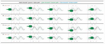
the graphs tries to imagine the movements of the tonearm (cartridge + shaft + carriage + CW) with respect to the stylus. For simplicity the eccentric motion is represented as an infinite linear sinusoid.
Some extreme conditions are assumed
A - zero friction - zero inertia - the carriage faithfully follows the movements of the stylus = 0 bending in each position.
B - some friction - zero inertia - the carriage follows the movements of the stylus with some delay = maximum bending at the turning point, zero in the center - The movement of the carriage is less wide than that of the stylus because the friction brakes the carriage
C - zero friction - some inertia - the carriage follows the movements of the stylus with less delay = maximum bending at the turning point, zero in the center - The movement of the carriage is wider than that of the stylus because the inertia continues to push the carriage even after the turning point
D - some friction - some inertia - the carriage follows the stylus movements with small delay, but continues when the stylus slows down = minimum bending in any situation - The movement of the carriage follows better that of the stylus because the inertia exceeds the friction when the side force tends to zero.
Certainly complex and variable movement which perhaps describes the one hypothesized by Niffy in the last paragraph. Tied to the amount of friction vs inertia
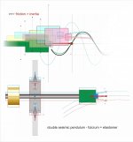
attachment 2
the graph tries to analyze the TA movement in the critical area of the turning point. The speed of the stylus tends to zero and then accelerates in the opposite direction; inertia instead reaches maximum positive to become instantly maximum negative.
Seen from the front the cantilever seems to have practically stopped for some time, trying to reach the side force needed to push the carriage on the opposite side.
It is perhaps like a double pendulum: the stylus rotates on the elastomer and this transmits the side force to the mass of the tonearm induced to go back and forth. Very complex to analyze
Stiction: maybe with jewel bearing, the sliding contact area is so small that a minimum rotation is enough to overcome it.
With ball bearings the situation is very different. There are multiple stictions: rail/wheel contact + contact of each sphere on inner and outer ring + cage friction; and certainly they do not act simultaneously: this perhaps explains the "lurching" effect that we both have noticed
carlo
sorry - if you are interested please download the first graphic: too fine details to be examined the usual way
the graphs tries to imagine the movements of the tonearm (cartridge + shaft + carriage + CW) with respect to the stylus. For simplicity the eccentric motion is represented as an infinite linear sinusoid.
Some extreme conditions are assumed
A - zero friction - zero inertia - the carriage faithfully follows the movements of the stylus = 0 bending in each position.
B - some friction - zero inertia - the carriage follows the movements of the stylus with some delay = maximum bending at the turning point, zero in the center - The movement of the carriage is less wide than that of the stylus because the friction brakes the carriage
C - zero friction - some inertia - the carriage follows the movements of the stylus with less delay = maximum bending at the turning point, zero in the center - The movement of the carriage is wider than that of the stylus because the inertia continues to push the carriage even after the turning point
D - some friction - some inertia - the carriage follows the stylus movements with small delay, but continues when the stylus slows down = minimum bending in any situation - The movement of the carriage follows better that of the stylus because the inertia exceeds the friction when the side force tends to zero.
Certainly complex and variable movement which perhaps describes the one hypothesized by Niffy in the last paragraph. Tied to the amount of friction vs inertia
attachment 2
the graph tries to analyze the TA movement in the critical area of the turning point. The speed of the stylus tends to zero and then accelerates in the opposite direction; inertia instead reaches maximum positive to become instantly maximum negative.
Seen from the front the cantilever seems to have practically stopped for some time, trying to reach the side force needed to push the carriage on the opposite side.
It is perhaps like a double pendulum: the stylus rotates on the elastomer and this transmits the side force to the mass of the tonearm induced to go back and forth. Very complex to analyze
Stiction: maybe with jewel bearing, the sliding contact area is so small that a minimum rotation is enough to overcome it.
With ball bearings the situation is very different. There are multiple stictions: rail/wheel contact + contact of each sphere on inner and outer ring + cage friction; and certainly they do not act simultaneously: this perhaps explains the "lurching" effect that we both have noticed
carlo
sorry - if you are interested please download the first graphic: too fine details to be examined the usual way
Attachments
Last edited:
Hi Carlo,
Excellent summary of situation.
One minor point. When there is some friction the bending will not be zero at the centre as dynamic friction is still present at this point. Dynamic friction will oppose the motion of the arm, acting to the right the entire time the carriage is moving to the left. If we add in stiction it gets a bit more complicated.
Niffy
So for someone who still hasn't put anything together, ball bearings is a dead
end if excellence is the main goal ?
end if excellence is the main goal ?
dynamic friction - of course, as well as other details that I deliberately neglected: I was interested in breaking down the influence of the various components of the phenomenon .
We should focus on the turning point area, where "strange things" happen. For example I wonder: the inertia to brake is somehow added to that to start again?
c
We should focus on the turning point area, where "strange things" happen. For example I wonder: the inertia to brake is somehow added to that to start again?
c

Last edited:
Niffy, Carlo,
Both of you did excellent analyses. Especially, these graphics are wonderful.
In my case, my arms fall into the case of C. I could not explain why damping through is a must for air bearing, but I could only tell from listening. Now, it is very well explained.
Jim
Both of you did excellent analyses. Especially, these graphics are wonderful.
In my case, my arms fall into the case of C. I could not explain why damping through is a must for air bearing, but I could only tell from listening. Now, it is very well explained.
Jim
Jim what did you make the arm rail mounting from? I like the way you have done this. The arm rail hangs lower from the mounting.
I notice you have used linear bearings for the vertical movement. I thought about doing this but instead decided to use a hard brass bush. Locking the vertical movement will be via a set screw from the rear of the upright.
I made a hardwood frame to extend the top platform of my SME 20. The frame is low. I wish I could use aluminum but I don't have the capacity to do so. The rails for horizontal movements are mounted on the hardwood frame. I use lead screws to adjust VTA. The pitch of lead screws is 2 mm. I can adjust vertical movements at .001 in. I am afraid that set screws may not be easy to use and high recommend to use lead screws. I have done three versions of this arm. It is really a pleasure to use it now.
Jim
So for someone who still hasn't put anything together, ball bearings is a dead
end if excellence is the main goal ?
It's largely down to budget and building skill. Ballrace bearings are much cheaper, easier to make and more readily available.
Really good results can be achieved with ballrace bearings. The first linear arm I built, about 25 years ago, was a mess. I got a lot wrong. I had the good fortune to have two identical high end decks (pink triangle anniversary) and two identical cartridges (ortofon mc3000) at my disposal. One deck was fitted with an SME V the other with my badly built first attempt. My arm easily bested the SME. Warrjon recently reported his ballrace based arm "smoking" his reference arm.
In developing my bearings I went through several stages starting with pivots made from sewing pins, vees from grub screws and steel wheels. These were as cheap to make as ballrace bearings but took a lot more work. The sound quality with these bearings was notably better than the ballrace version. The move to jeweled bearings and all the tungsten carbide elevated the sound quality by a substantial amount. If you want the best possible mechanical bearing then I would definitely recommend my system.
I believe that I am the only one who has a working arm with jeweled bearings, tungsten carbide rails and wheels. (I think Joe is close to a working arm). I would really like to have some feedback from other builders who have built both ballrace and jeweled/carbide to see if their results match mine. So far you are relying on a sample size of one.
Niffy
Niffy, Carlo,
Both of you did excellent analyses. Especially, these graphics are wonderful.
In my case, my arms fall into the case of C. I could not explain why damping through is a must for air bearing, but I could only tell from listening. Now, it is very well explained.
Jim
Hi Jim,
The addition of a damping trough to an airbearing linear arm such as yours is normally done with the aim of controlling the linear motion of the arm.
I have a different theory. I don't think that additional damping in the lateral plane is actually necessary. The primary excitement frequency laterally, eccentricity, is 3-4 octaves below the lateral resonance of the arm so is going to have minimal effect. However vertically the primary excitement frequency, warps, is only 1-2 octaves below the vertical resonance and is therefore much more likely to cause excitement. Additionally the arm is much more inclined to want to "bounce" vertically as this is in line with the main restorative force, gravity.
The sonic benefits are more likely to be due to the additional damping in the vertical plane rather than in the horizontal.
Niffy
Niffy,
It is possible. In my opinion, vertical damping is more important than lateral. However, it is not possible to do vertical damping only with a through. Although I designed the paddle with more vertical damping, lateral damping will always be there. I believe adding some controlled lateral friction helps to reduce inertia. You and Carlo have clearly outlined it.
Jim
Hi Jim,
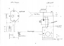
I originally considered using a lead screw but the upright does not have enough room to use a lock nut easily. So I decided to use a linear shaft with a bush. The drawing does not show the VTA lock screw but there will be 1 each side coming out the back of the upright so locking is easy with a thumb screw.
I like how you mounted the rail support to the VTA adjuster, my way was a lot more complicated so I will steal your idea.
Attachments
Hi Jim,
I originally considered using a lead screw but the upright does not have enough room to use a lock nut easily. So I decided to use a linear shaft with a bush. The drawing does not show the VTA lock screw but there will be 1 each side coming out the back of the upright so locking is easy with a thumb screw.
I like how you mounted the rail support to the VTA adjuster, my way was a lot more complicated so I will steal your idea.
Hi Warrjon,
I see what you did. It is nice.
Jim
It's largely down to budget and building skill. Ballrace bearings are much cheaper, easier to make and more readily available.
Really good results can be achieved with ballrace bearings. The first linear arm I built, about 25 years ago, was a mess. I got a lot wrong. I had the good fortune to have two identical high end decks (pink triangle anniversary) and two identical cartridges (ortofon mc3000) at my disposal. One deck was fitted with an SME V the other with my badly built first attempt. My arm easily bested the SME. Warrjon recently reported his ballrace based arm "smoking" his reference arm.
In developing my bearings I went through several stages starting with pivots made from sewing pins, vees from grub screws and steel wheels. These were as cheap to make as ballrace bearings but took a lot more work. The sound quality with these bearings was notably better than the ballrace version. The move to jeweled bearings and all the tungsten carbide elevated the sound quality by a substantial amount. If you want the best possible mechanical bearing then I would definitely recommend my system.
I believe that I am the only one who has a working arm with jeweled bearings, tungsten carbide rails and wheels. (I think Joe is close to a working arm). I would really like to have some feedback from other builders who have built both ballrace and jeweled/carbide to see if their results match mine. So far you are relying on a sample size of one.
Niffy
Thanks a lot for your input, it's really appreciated. I guess I will rethink this project again to come up with a similar solution to what you have made.
No need to go the extra mile just to come up with the same solution later on. 🙂
Back to the drawing board again 😎
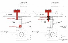
Hi Warren, a little mod could help to avoid any possible chattering - two counteracting actions: the ideal would be two screws one against the other, but a strong spring (inside some silicon glue) may work.
The same for linear bearings at the base: plastic Igus maybe better than linear ball bearings, imho
carlo
The same for linear bearings at the base: plastic Igus maybe better than linear ball bearings, imho
carlo
Attachments
- Home
- Source & Line
- Analogue Source
- DIY linear tonearm