Ps.
I agree with Jim. The terminator is an ok arm but has many flaws. The low pressure exasperated the air spring effect plus the carriage is a poor use of the available mass.
Niffy
I agree with Jim. The terminator is an ok arm but has many flaws. The low pressure exasperated the air spring effect plus the carriage is a poor use of the available mass.
Niffy
Hi,
why? Because we can and because we like to 😎
Besides not everyone likes a bulky, noisy air pump in his listening room ... or another power line dependant device.
If You're interested in linear air arms, well, there are enough entries to digest and the possibility to open a own thread.
jauu
Calvin
no, I don't have enough knowledge on the subject, I would make a fool out of myself!
BTW you should be on the lab developing new Buffers instead of being on mechanical topics! 😱😎
Ps.
I agree with Jim. The terminator is an ok arm but has many flaws. The low pressure exasperated the air spring effect plus the carriage is a poor use of the available mass.
Niffy
Can you please elaborate more for people like me who have no knowledge?
What is exactly this spring effect? In the vertical axes or horizontal?
Shouldn't low pressure assure low chattering effect?
Why would a carriage be a poor use of mass?
If you could put this into audible effect, what would be the consequences of this flaws?
Do you have the terminator? Have you had a chance of trying it?
I can only comment in terms of sonic performance: It blew away my VPI 12.5 tonearm, so it was convincing on my end, but I am interested in knowing more about your technical opinion.
Air pump is very quiet, and it can easily be kept on the next room if you allow a small hole in the wall to pass the air pipe.
If low pressure is a concern, how come I hear clear sonic improvement as I lower the air pressure?
I am very interested in understanding a bit about this subject.
Last edited:
Stefanoo,
Your question is not stupid at all.
For a air bearing arm, the biggest obstacle is air compressor. Even for low air pressure compressor, its noise can be too much for quiet listening session. So, you need separate space to host the compressor. Another obstacle is the cost of air compressor. Low air pressure compressor is not too expensive. But I won’t recommend low air pressure air bearing arms personally.
I personally don’t recommend Terminator tonearm for two reasons.
1. Its bearing is not stiff enough.
2. Its construction is not rigid and compact enough.
Three are no variations for high air pressure air bearing arms. The higher pressure, the stiffer the bearing is. This is what we want for a high performance tonearm.
Hope this helps.
Jim
Thank you for not considering this question stupid!
Sorry what is the bearing in this case? is it the carriage? Or the two pivots spikes on the tonearm?
In what way would the construction not be compact?
The word, bearing, refers to area that one triangle is on top another triangle with air gap in between. This is actually an air bearing.
I said it is not compact. I meant that it has too many parts hanging under the air bearing. The whole construction is not rigid.
I said it is not compact. I meant that it has too many parts hanging under the air bearing. The whole construction is not rigid.
In what way does it have too many parts?
The arm I have in my hand has
1) one slider, the long "V-shaped" piece of aluminum with micro-holes where the air goes through.
2) the carrier (the smaller "V-shaped" piece of aluminum) riding on air on top of the slider.
On the carrier there are brackets glued to it where the armwand rests on with 2 spikes (pivoted). Armwand is really short for improved rigidity.
In what way would a high pressure airbearing be superior to that?
I am trying to understand and my apologies for my very limited knowledge on the subject.
I just go by logic, and assume that any part that floats on air with minimum pressure will suffer less from noise coming from air source, needs less performing air pump, less noise and space and money needed for air supply.
This is confirmed from listening, like I said, when I lower air pressure sounds improves dramatically.
Could rigidity be improved by using materials other than aluminum? Is this the rigidity you are referring to? Or would you mind explaining more in details the flaws in rigidity you see with this design and how could they be improved?
Last edited:
Hi Stefano,
In between the two parts of an air bearing is a layer of compressed air that keep the parts a certain distance from each other. If you apply a load or force to one part this distance will change, the greater the force the greater the change. If you remove the force the distance will return to its former magnitude. If the force is removed suddenly the part will move back to its original position rapidly but as it will now have momentum it will over shoot then move back and forth until it finally settles in its starting position. This is exactly what happens with any type of spring. The air in the gap of an air bearing is a spring, it's just one made of air rather than steel but apart from that they are the same. The energy fed into the carriage from the stylus/record acts as the force in this case. It may be useful to read my posts on effective mass from a couple of pages ago.When you combine the air spring with the mass of the arm you will have a resonant system with a fundamental resonant frequency, this is unavoidable. Any vibration at this frequency will be amplified. The carriage will "bounce" at this frequency causing the cartridge to move relative to the record creating an unwanted signal.
The stiffer the air spring the higher this resonant frequency will be.
As you increase in frequency the amount the cartridge body moves relative to the stylus reduces (see effective mass post). If you make the air spring very stiff (high pressure) you push the bearings resonance up to a high frequency. At this higher frequencies there is much less movement and therefore less energy so the amount the bearing is excited is much less.
High pressure bearings are different from the Terminator bearing in that they surround the rail and apply pressure from all sides. If you increase the pressure the carriage remains in the same position relative to the rail and the stiffness of the air spring increases. The Terminator only supplies air from underneath and has only the carriage mass acting downwards. If you increase air pressure the carriage moves upwards and the air gap increases. As the air gap increases the air spring stiffness decreases. The opposite of with a high pressure system. You get maximum air spring stiffness at the lowest pressure which is why your arm will sound at its best at the lowest possible air pressure when the air gap is at its smallest. With the Terminator the pressure in the air gap is always the same and is proportional to carriage mass (force/area=pressure). Increasing supply pressure only increases the air gap due to greater flow rate. With a high pressure system the pressure in the air gap is proportional to the supply pressure and can therefore be much higher.
On to where I said a poor use of the available mass. There is only so much mass that can be used for the entire carriage. When designing I call this my mass budget. I want to spend every gram of that budget as economically as possible. Every gram has to be increasing the rigidity and improving the resonant character of the carriage. By splitting the carriage into two parts, to separate the vertical and lateral bearings, you have immediately lost half your budget. An articulated joint is never going to be as rigid as a solid beam. Where it is VERY true that reduction of arm length massively improves resonant character the choice of shape and material are also just as important. A solid flat aluminium plate is inefficient compared to a tube or box section in carbon fibre.
If I were purchasing a commercial arm I would choose the terminator over virtually any pivoted arm. I am very aware that this is a substantially cheaper arm than most air bearing arms. Arms like the Kuzma or Air Tangent cost considerably more and do have the advantage of very high tolerance high pressure bearings and single peace carriages made of more exotic materials. But the Terminator does have the short arm that makes a big difference. Yes technically there are flaws to the Terminator design. Yes they could be remedied but not for the same price. The terminator style of arm is also very diyable without the need for expensive equipment.
Niffy
Last edited:
Stefanoo,
The Terminator arm has 2 diamond brackets, 2 v-cups on the diamond brackets and 2 spikes on the arm wand. In my opinion, there are too many parts already. The pivots and air bearing( slider) are two different and separated parts. Any change of air pressure will cause micro movements of 2 pivots. And the slider is just a piece of triangle floats on low pressure air. If the pressure is high, the top v-shaped aluminum will be pushed up since there is no force to hold it down. Its micro movements are almost inevitable. These micro movements will be amplified through the diamond brackets since the carriage is hanging low under the slider. Then, the 2 pivots will move, too.
This is what I meant it is not rigid enough.
For a high pressure air bearing arm, its bearing, its pivot and its slider are all in one component. It is a closed cylinder. It can’t be pushed towards one direction. Higher air pressure will make the pivot even stiffer and more accuracy. This kind of air bearing has highly accuracy, precision and repeatability. This is a rigid construction. But its shortcoming is it requires a high pressure air compressor.
In Niffy’s post, he used a very interesting word, air spring. I can say this. If air spring does exist, it is very very tiny in this kind of air bearing. Its air gap is 4 microns. If the air pressure is 50 psi for a 200 g load, I guess its air spring is almost none.
Jim
Stefanoo,
The Terminator arm has 2 diamond brackets, 2 v-cups on the diamond brackets and 2 spikes on the arm wand. In my opinion, there are too many parts already. The pivots and air bearing( slider) are two different and separated parts. Any change of air pressure will cause micro movements of 2 pivots. And the slider is just a piece of triangle floats on low pressure air. If the pressure is high, the top v-shaped aluminum will be pushed up since there is no force to hold it down. Its micro movements are almost inevitable. These micro movements will be amplified through the diamond brackets since the carriage is hanging low under the slider. Then, the 2 pivots will move, too.
This is what I meant it is not rigid enough.
For a high pressure air bearing arm, its bearing, its pivot and its slider are all in one component. It is a closed cylinder. It can’t be pushed towards one direction. Higher air pressure will make the pivot even stiffer and more accuracy. This kind of air bearing has highly accuracy, precision and repeatability. This is a rigid construction. But its shortcoming is it requires a high pressure air compressor.
In Niffy’s post, he used a very interesting word, air spring. I can say this. If air spring does exist, it is very very tiny in this kind of air bearing. Its air gap is 4 microns. If the air pressure is 50 psi for a 200 g load, I guess its air spring is almost none.
Jim
But how many parts would a kuzma airline have?
Looking at pictures, it seems it is made up of many parts.
I am not an expert and I never compared the kuzma with the terminator, but for an implementation standpoint, terminator seems to be way simpler.
Simpler doesn't necessary mean better, I am sure the kuzma is a more complex and more exotic design.
The diamond v-cups are glued thus forming virtually one part so do speak.
So the carriage, the slider and the arm on pivot is all the terminator is made of.
It is very interesting the concept of the spring and the less the air pressure the stiffer the spring, which happily, the theory matches the listening experience.
Also explains why adding weight to the pivot points increase the sound significantly, which equals I guess adding mass and increasing the stiffness of the spring thus pushing resonant frequency to a higher level.
Regarding carbon fiber tube, I think the developer has tried that as well, but found the flat armwand sounded better (I might be wrong on this).
I would be very interested in improving this arm, if improvements are possible.
I don't care if it costs good money to improve it.
If you guys that ar great experts in the field would like to suggest improvements I will be very happy to try them.
Stefano,
When I said there are too many parts, I only refer to the critical area, i.e. the bearing and pivot. For Kuzma airline, all the movements, vertical, horizontal and linear guiding force are all completed in one component. So, actually, Kuzma airline has less part than the Terminator has. For the Terminator, its slider does the horizontal movements and provides linear guiding force. Its spikes do the vertical movements. These two parts are different components. The arm wand sits freely on the v-cup while the slider does the horizontal movements. I simply don't like this kind of construction. The connection of these two parts are simply too loose. In other words, it is not rigid.
Jim
Last edited:
Stefano,
When I said there are too many parts, I only refer to the critical area, i.e. the bearing and pivot. For Kuzma airline, all the movements, vertical, horizontal and linear guiding force are all completed in one component. So, actually, Kuzma airline has less part than the Terminator has. For the Terminator, its slider does the horizontal movements and provides linear guiding force. Its spikes does the vertical movements. These two parts are different components. The arm wand sits freely on the v-cup while the slider does the horizontal movements. I simply don't like this kind of construction. The connection of these two parts are simply too loose. In other words, it is not rigid.
Jim
Yes. That's exactly what I meant when I said an articulated joint is never as stiff as a solid beam.
Niffy
Hi Jim, Stefano,
Air spring is a very real phenomenon. I'll expand on my previous post to try and make it more clear.
Imagine a Terminator style arm. It has a carriage mass of 150g and a bearing surface area of 15 square centimetres. It flots on a pressurized cushion of air that applies a pressure to the underside of the carriage. The pressure required to support the carriage will be 10g/cm^ 2. If it were more than this the carriage would accelerate upwards and if it were less than this the carriage would accelerate downwards. As the carriage remains stationary we know that the pressure is exactly 10g/cm^ 2. If the supply pressure is increased the pressure in the air gap increases causing the carriage to move upwards. This increases the gap around the edge of the bearing allowing more air to escape lowering the pressure until the pressure is again 10g/cm^ 2 and the carriage is again stationary. As previously mentioned the air in the gap acts as a spring.The length of this spring is the thickness of the air gap.
Now imagine a length of steel spring as it is easier to picture. Cut two pieces from this to make two springs one 5cm long and one 10cm long. Place a mass on the 5cm spring that compresses it by 1cm. Now place the same mass on the long spring. The top 5cm half will compress by 1cm and the bottom half will compress by 1cm giving a total compression of 2cm. Doubling the length will halve the stiffness of the spring. Now bounce the mass on each of the springs. The mass will bounce more rapidly on the shorter-stiffer spring, it will have a higher resonant frequency. The same is true of the Terminator bearing, increase the spring length (air gap) and you decrease the spring stiffness and decrease the resonant frequency.
Now to compare to a high pressure system.
Take the mass from the spring/mass model and place it on a very short spring (this corresponds to the very small air gap that this type of bearing utilises) now make the spring very thick and stiff (this corresponds to the high pressure). Now add a second identical spring to the top of the mass (this is because the air gap/air spring surrounds of the bearing). Now bounce the mass. It will bounce at a vastly higher rate.
The stiffness of a high pressure bearing is going to be inexcess of a thousand times as great as a low pressure system. This can result in the resonant frequency of the system being pushed maybe 50 times as high. An increase in rigidity of this magnitude could reduce the amount the cartridge body moves at the air spring resonant frequency by as much as 16dB.
Niffy
Stefanoo,
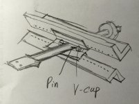
Here is an idea for you. However, it is just an idea. I can’t say it will work perfectly for sure. You need to judge by yourself if it is worth to do it. It may be beyond diyer’s capacity. The top slider and bottom slider have to be lined up very precisely.
Jim
Here is an idea for you. However, it is just an idea. I can’t say it will work perfectly for sure. You need to judge by yourself if it is worth to do it. It may be beyond diyer’s capacity. The top slider and bottom slider have to be lined up very precisely.
Jim
Attachments
Thank you very much for your explanation.
But practically though, the air supply will not be constant will have chattering effect. Th higher the pressure the higher this effect on the cartridge.
While it is true that the stiffer spring effect will have resonance beyond audio band, the noise of the air supply itself will be somehow picked up by the micro phonic transducer. Can this consideration be realistic?
A lower pressure arm, though suffers more on resonant frequency, which could technically be mitigated by choosing proper compliance, will have less chattering problems. Is this statement correct in your opinion?
Also another question: if you increase the mass to make it stiffer and increase air supply. Won't the equivalent horizontal mass increase as well and make vertical and horizontal mass eve more different to each other thus causing more phase distortion (assuming grooves are cut at 45deg angle)?
Stefanoo,
Here is an idea for you. However, it is just an idea. I can’t say it will work perfectly for sure. You need to judge by yourself if it is worth to do it. It may be beyond diyer’s capacity. The top slider and bottom slider have to be lined up very precisely.
Jim
I will have to digest this idea.
At first glance it seems very complicated to implement. How are the two slides going to be installed so precisely. Carrier has X-shape and would have to be CNCed.
Why would this solution produce an improvement?
What is the armwand resting on? Ball bearings instead of spikes?
Btw..congrats your hand drawing skill is amazing!
....The terminator style of arm is also very diyable without the need for expensive equipment.
Niffy
... I got mine (in DIY) for 30EURO ....
Believe me ... it's music, I like it ....
Top.
Karel
Hi,
J have almost baught all j need and can you tell me what you think about my project
Thanks to all, j have copy most of what j have found.
My idea is to use an aluminium tube with a standand plexi tube arround in order to secure the tonearm

J have some questions :
What should be the lenght of the spacer ?
10 mm plexiglass is enough or too much for the support
What about the tonearm. J wanted to use an Arrow Carbon / Aluminium Carbon / aluminium
Regards
Philippe
Hi Philippe,
Looks good so far. A couple of questions/suggestions.
Is the blue circle in your diagram the plexiglass tube? Is it attached to the carriage or the rail? I wouldn't attach it to the carriage as it will add unnecessary mass that will increase bearing friction and it will have it own resonant character that will colour the sound. If it's a dust cover/derail protection attached to the rail..excellent, though it appears from your diagram that those functions are already covered by the aluminium which I assume is a box section.
Rather than the inverted L shaped headshell I would recommend a solid block style. Have a look at the headshell design used by Colin (this epic threads originator) in his later designs or those of the clearaudio arms.
As to the length of the spacer. Just long enough to clear the rail. Shorter is more rigid, more rigid is better.
The thickness of the bearig yoke is a trade off between mass and rigidity. Acrylic is low density at only 1.15g/cm^ 3. A couple of millimetres difference will only change the total mass by a couple of grams.
Arrows are a excellent source of arm tubes.
Niffy.
Thanks for your help
The round grey is an aluminium plain tube wich will be cut with digital spécial machine.
The line point ...... in the grey tube represents what we have to delete
The blue circle represents the plexiglass tube. The cut is not represented on the plexiglass tube . The plexiglass tube will be fix just by glue (uv) or two small screws, in fact the target of the plexi is to secure the tonearm.
Sorry for my poor English and french on this drawing

Last edited:

- Home
- Source & Line
- Analogue Source
- DIY linear tonearm