How to calculate effective mass
Hi all,
Here is a copy of the post I made in the effective mass thread. This mainly deals with how to calculate vertical effective mass, which is the same method for both linear tracking arms and pivoted arms, but also does touch on how to calculate lateral effective mass for pivoted arms as well. The lateral effective mass for a linear tracking arm is easy to calculate as it is just the total mass of the carriage (including cartridge etc).
Calculating a tonearms effective mass is theoretically simple but can be difficult and laborious.
To calculate the vertical effective mass first divide the arm into sections. A larger number of smaller sections will give a more accurate result. For example divide the arm tube into 5mm long sections. Calculate the mass of each section. This is done by calculating the volume of each section and multiplying this by the density of the material it is made from. This can be very difficult for commercial arms as you will probably not know the exact material, and its density. Nor will wall thickness of tubular sections be readable apparent. For diy arms this is much easier as you should know what you are making your arm from.
Next calculate where the centre of mass of each section is and measure/calculate the distance from this to the vertical pivot point. This has bo be a straight line distance, the height above/below the pivot as well as the horizontal distance is important. So a bit of Pythagoras will be needed.
Next SQUARE this distance and multiple by the sections mass. Do this for every section. A spread sheet will be your friend here. Then add the results for all the sections together. I find that doing this in named segments makes this easier, eg headshell, arm tube, counterweight.
Now divide this total by the straight line distance from the vertical pivot to the stylus SQUARED. Again the vertical hight of the pivot is important, a bit more Pythagoras.
This is your vertical effective mass....Almost.
A couple of additional points.
Do not attempt to model the counterweight as a single section as this will give a very inaccurate result. With a typical underslung weight the top front edge will be quite close to the pivot and the bottom rear quite far away. The weight should be divided into sections vertically as well as horizontally. Even with a simple shape like a circular disc the maths can get a bit involved but is not complicated, high school level. For those with a bit of calculus under their belts it is relatively easy to integrate for the whole weight.
Make sure you account for all the components that move in the vertical plain. Eg mounting hardware, finger lift, cartridge tags etc.
Normally the mass of the cartridge is just added to the effective mass of the arm. This is not entirely accurate. Ideally the effect of the cartridges mass should be calculated from its centre of mass which is normally about 10mm above and 10mm behind the stylus. With long arms just adding the mass of the cartridge to the arms effective mass gives a pretty good answer. With short arms, as found on many linear trackers, the cartridges centre of mass must be used to determine its contribution to overall effect mass. Failing to do so can easily result in an error of several grams.
Calculating the horizontal or lateral effective mass of the arm is basically the same as for the vertical. Again divide the arm into sections and ascertain mass and centre of mass and distance to the vertical axis. If calculating for an arm with a standard yoked bearing remember to add all the components that only rotate horizontally that were not included in the vertical model eg the bearings yoke.
We tend to call the point the arm pivots around the pivot point. In reality it is not a point but a line and is more accurately called the pivot axis. Many arms have a lateral pivot axis that is twisted horizontally to be perpendicular to the offset angle, eg Rega and SME. When calculating the lateral effective mass of an arm with an offset pivot axis the horizontal distances to a section need to be measured at right angles from this axis and NOT from the centre of the armtube between the bearings. For instance, take a 9" tonearm with the vertical pivot axis level with the record surface and offset by 22°. The effective arm length will be 223mm. However the distance from the stylus to the pivot axis is only 207mm. This makes calculating the lateral effective mass of arms with offset bearings a bit more tricky.
Calculating the horizontal effective mass of a linear tracking arm is easy, it's just the mass of the arm.
Ideally the determination of the effective mass of the arm should be done as part of the entire design from the start and not as an afterthought. It is relatively easy to add extra features to the spread sheet used to calculate effective mass. Using these you can tune the design of your arm to ideally match your chosen cartridge. As you should know your cartridges compliance you can determine the cantilever resonance. If you have set up your spread sheet neatly you should easily be able to add in calculations to determine tracking force. Then by adjusting the position and size of the counterweight you can fine tune your design so that when the correct tracking force is set the effective mass will be perfect.
Niffy
When I made the above post I was unable to include any diagrams so here's a quick one which should simplify the explanation.

Niffy
Niffy
Effective mass explanation.
Hi all,
Knowing how to calculate effective mass is one thing but what does effective mass actually do?
The suspension in a cartridge that supports the cantilever is basically a spring. This spring has a compliance. Compliance is a measure of how far the spring will deflect for a given force. The specification of a cartridge is in um/mM. 1um is one millionth of a metre or one thousandth of a millimetre. 1mN is one thousandth of a Newton or about one tenth of a gram (0.0981g) With a cartridge with a compliance of 15um/mN a force of 1mN will cause the stylus to move by 15um.
If you support a mass on a spring and disturb it will bounce up and down at a particular frequency. This is called the resonant frequency of the spring/mass system. The mass in our case is the effective mass. In our simple model of a mass sitting on a spring the spring sits on a supporting surface. See diagram.

If you vibrate the supporting surface at the resonant frequency the mass on the spring will bounce up and down a lot, more than the amount the surface was moving.
If you vibrate the surface at a frequency much lower than the resonant frequency the mass will move up and down with the surface. The amount the mass moves will be the same as the amount the surface moves. In other words there will be no relative movement between the mass and surface
If you vibrate the surface at a frequency much higher than the resonant frequency the mass will move only a small amount relative to the movement of the surface. The higher the frequency the less the mass will move.
In this model the surface is the record, the spring is the cartridge compliance and the mass is the effective mass of the arm/cartridge. So far I have only been looking at vertical movement though exactly the same mechanism operates for lateral movement. Low frequency vertical movement is due to record warps. Warps in records occur between 0.55hz and about 6hz. Low frequency lateral movement is mainly due to record eccentricity and occurs at 0.55hz. High frequency movement is due to the modulation of the groove. The audio bandwidth starts at 20hz. Most records are recorded in mono below about 120hz, lateral modulation only to prevent the stylus from jumping out of the groove. So vertical modulation is from 120hz and lateral from 20hz.
What you want to do is position the resonant frequency so that it is safely above the frequency of warps for vertical movement and eccentricity for lateral movement. It also wants to be below the audio bandwidth. The normally recommended frequency is 10hz. This is as far as most articles on effective mass go.
There is a lot more to it.
The ideal situation is to have the cartridge move freely to follow warps and eccentricities but not move at all at audio frequencies. As previously mentioned in the spring/mass model the mass (cartridge) does move a bit at high frequencies. The amount it moves is dependent upon not only the frequency but also the mass. A higher mass will move a smaller amount. You know this from everyday experience, it's easier to shake a lightweight object than a heavy one. The amount the cartridge moves relative to the modulation of the groove can be modelled using a transfer function. Don't worry I've done all the maths for you. The following graph shows the transfer function of two arm/cartridge combinations. One with a resonant frequency of 10hz and one with a resonant frequency of 3.5hz. These would equate to a 15um/mN cartridge with effective masses of 17g and 140g. I've also highlighted the frequency at which lateral movement due to eccentricity occurs, 0.55hz. And the range over which vertical movement due to warps occur, 0.55-6hz.

I haven't mentioned damping characteristics of the cartridge suspension but they were involved in producing the graph, I didn't want to overcomplicate things.
Ideally you want the lines of the graph to be at zero below the points where warps and eccentricity occur and to be as low as possible in the audio bandwidth. The vertical axis is in decibels. A -10dB level means that the cartridge body is moving one tenth the amount the stylus is moving, -20dB means it's moving one hundredth the amount.
Let's examine what is happening at 50hz, a nice deep bass note. With the cantilever resonance of 10hz the cartridge body movement is only 9.7dB down. With the cantilever resonance at 3.5hz the movement is now down 19dB, that a 9.3dB improvement. That means the cartridge is moving almost one tenth the amount. Unfortunately the resonant peek is slap bang in the middle of the frequency range where warps occur.
BUT warps are vertical not lateral. 3.5hz is safely above any lateral low frequency movement, 0.55hz. This is one of the advantages of linear tracking tonearms. You have high lateral effective mass that controls the cartridge better at low frequencies where there is only lateral modulation of the groove anyway
Some have attacked linear tracking tonearms for having different effective masses in the vertical and lateral planes. There isn't actually any problem here. Less movement of the cartridge body is an improvement regardless. Plus at higher frequencies, dependent upon the bearing design, play in the bearings comes into play. At higher frequencies the carriage no longer moves laterally in its entirety but begins to rotate about its centre of mass. The amount it rotates is incredibly small (think arc-seconds) and has no effect on lateral tracking angle. The lateral effective mass is now calculated as if it were pivoting about this point. This lowers the effective mass to be similar to the vertical. So you have high effective mass where you need it most, low frequency, where the modulation is lateral only and by the time you get high enough is frequency that there is vertical modulation the effective masses are about the same anyway. Win win.
I hope this clarifies things and gets rid of at least one myth about linear tracking arms.
Niffy
Hi all,
Knowing how to calculate effective mass is one thing but what does effective mass actually do?
The suspension in a cartridge that supports the cantilever is basically a spring. This spring has a compliance. Compliance is a measure of how far the spring will deflect for a given force. The specification of a cartridge is in um/mM. 1um is one millionth of a metre or one thousandth of a millimetre. 1mN is one thousandth of a Newton or about one tenth of a gram (0.0981g) With a cartridge with a compliance of 15um/mN a force of 1mN will cause the stylus to move by 15um.
If you support a mass on a spring and disturb it will bounce up and down at a particular frequency. This is called the resonant frequency of the spring/mass system. The mass in our case is the effective mass. In our simple model of a mass sitting on a spring the spring sits on a supporting surface. See diagram.
If you vibrate the supporting surface at the resonant frequency the mass on the spring will bounce up and down a lot, more than the amount the surface was moving.
If you vibrate the surface at a frequency much lower than the resonant frequency the mass will move up and down with the surface. The amount the mass moves will be the same as the amount the surface moves. In other words there will be no relative movement between the mass and surface
If you vibrate the surface at a frequency much higher than the resonant frequency the mass will move only a small amount relative to the movement of the surface. The higher the frequency the less the mass will move.
In this model the surface is the record, the spring is the cartridge compliance and the mass is the effective mass of the arm/cartridge. So far I have only been looking at vertical movement though exactly the same mechanism operates for lateral movement. Low frequency vertical movement is due to record warps. Warps in records occur between 0.55hz and about 6hz. Low frequency lateral movement is mainly due to record eccentricity and occurs at 0.55hz. High frequency movement is due to the modulation of the groove. The audio bandwidth starts at 20hz. Most records are recorded in mono below about 120hz, lateral modulation only to prevent the stylus from jumping out of the groove. So vertical modulation is from 120hz and lateral from 20hz.
What you want to do is position the resonant frequency so that it is safely above the frequency of warps for vertical movement and eccentricity for lateral movement. It also wants to be below the audio bandwidth. The normally recommended frequency is 10hz. This is as far as most articles on effective mass go.
There is a lot more to it.
The ideal situation is to have the cartridge move freely to follow warps and eccentricities but not move at all at audio frequencies. As previously mentioned in the spring/mass model the mass (cartridge) does move a bit at high frequencies. The amount it moves is dependent upon not only the frequency but also the mass. A higher mass will move a smaller amount. You know this from everyday experience, it's easier to shake a lightweight object than a heavy one. The amount the cartridge moves relative to the modulation of the groove can be modelled using a transfer function. Don't worry I've done all the maths for you. The following graph shows the transfer function of two arm/cartridge combinations. One with a resonant frequency of 10hz and one with a resonant frequency of 3.5hz. These would equate to a 15um/mN cartridge with effective masses of 17g and 140g. I've also highlighted the frequency at which lateral movement due to eccentricity occurs, 0.55hz. And the range over which vertical movement due to warps occur, 0.55-6hz.
I haven't mentioned damping characteristics of the cartridge suspension but they were involved in producing the graph, I didn't want to overcomplicate things.
Ideally you want the lines of the graph to be at zero below the points where warps and eccentricity occur and to be as low as possible in the audio bandwidth. The vertical axis is in decibels. A -10dB level means that the cartridge body is moving one tenth the amount the stylus is moving, -20dB means it's moving one hundredth the amount.
Let's examine what is happening at 50hz, a nice deep bass note. With the cantilever resonance of 10hz the cartridge body movement is only 9.7dB down. With the cantilever resonance at 3.5hz the movement is now down 19dB, that a 9.3dB improvement. That means the cartridge is moving almost one tenth the amount. Unfortunately the resonant peek is slap bang in the middle of the frequency range where warps occur.
BUT warps are vertical not lateral. 3.5hz is safely above any lateral low frequency movement, 0.55hz. This is one of the advantages of linear tracking tonearms. You have high lateral effective mass that controls the cartridge better at low frequencies where there is only lateral modulation of the groove anyway
Some have attacked linear tracking tonearms for having different effective masses in the vertical and lateral planes. There isn't actually any problem here. Less movement of the cartridge body is an improvement regardless. Plus at higher frequencies, dependent upon the bearing design, play in the bearings comes into play. At higher frequencies the carriage no longer moves laterally in its entirety but begins to rotate about its centre of mass. The amount it rotates is incredibly small (think arc-seconds) and has no effect on lateral tracking angle. The lateral effective mass is now calculated as if it were pivoting about this point. This lowers the effective mass to be similar to the vertical. So you have high effective mass where you need it most, low frequency, where the modulation is lateral only and by the time you get high enough is frequency that there is vertical modulation the effective masses are about the same anyway. Win win.
I hope this clarifies things and gets rid of at least one myth about linear tracking arms.
Niffy
Hi Niffy,
Thanks for your excellent and very helpful post!
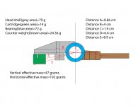
I calculated the vertical effective mass for my arm. It is actually just an estimation because I couldn’t accurately determine some of parameters, such as sectional mass, center of mass, etc. It is also because I tried to make shapes simpler and I didn't calculate the mass by using exact shapes. I also did the counter weight as one piece. Anyway, please see the drawing. The full carbon fiber head shell/carriage is much heavier than I expected. It is 79 grams! I calculated twice to just make sure there was no mistakes. I used 1.55 gram/cubic centimeter density for carbon fiber and an online calculator.
Jim
Thanks for your excellent and very helpful post!
I calculated the vertical effective mass for my arm. It is actually just an estimation because I couldn’t accurately determine some of parameters, such as sectional mass, center of mass, etc. It is also because I tried to make shapes simpler and I didn't calculate the mass by using exact shapes. I also did the counter weight as one piece. Anyway, please see the drawing. The full carbon fiber head shell/carriage is much heavier than I expected. It is 79 grams! I calculated twice to just make sure there was no mistakes. I used 1.55 gram/cubic centimeter density for carbon fiber and an online calculator.
Jim
Attachments
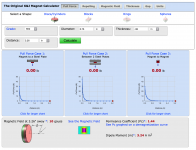
I am also thinking about how to implement the damping device. I know silicone trough works wonderfully but I am trying to do it differently. I am thinking of Eddy current device. However, I am afraid of the magnetic field may impact cartridge. I did some calculation on line at following site.
https://www.kjmagnetics.com/calculator.asp
In my design, the magnet is about 3.25” away from the cartridge, but the magnetic field still has 10 gauss to reach the cartridge. I am not 100% sure if it is ok. Please attached image. Anyway, I may just make a tubular silicone trough for safety.
https://www.kjmagnetics.com/calculator.asp
In my design, the magnet is about 3.25” away from the cartridge, but the magnetic field still has 10 gauss to reach the cartridge. I am not 100% sure if it is ok. Please attached image. Anyway, I may just make a tubular silicone trough for safety.
Attachments
Hi Jim,
It's looking pretty good so far. A vertical effective mass of 46g is rather high. Correct me if I'm wrong, I understand that your cartridge has a compliance of 15um/mN. This would give your arm a vertical cantilever resonance of 6hz which is entering the range where warps occur. With your combination of central and peripheral clamps most warps should be entirely flattened so you may be ok. In the early stages of my design work I built a measurement rig and measured the actual level of warps in a random sample of my record collection and the effects of different clamps.
This is just a hypothesis based on these measurements. I think that the higher frequency warps, those that occur in the 5-6hz range, may be due to ripples in the thickness of the record itself and as such would be impossible to entirely eradicate with clamping. These are however very low amplitude, about 20um, so may not be too problematic especially if the arm is well damped as yours is. I did take these points into consideration when I recommend a 8hz vertical resonance. 8hz would require an effective mass of 26g. It looks like you have not included the counterweight in your diagram. If this is the case effective mass will be higher still pulling the resonant frequency even lower.
The lateral cantilever resonance would be 3hz which is a bit lower than I would have aimed for but should be ok if your deck is well isolated, which I assume it is.
If your cartridge has a compliance of 9um/mN then the effective masses you've shown will be very good giving vertical resonance of 8hz and lateral of 3.8hz.
I haven't studied eddy current damping in detail so I'm not right person to advise you on that subject.
Niffy
Hi Niffy,
First, the horizontal effective mass should be 189 g, not 192.
No. I didn't include the weight because I have no idea how much it will be.
I have three cartridges. Two of them have compliance 15. And, one, a modificated Denon DL-103R, has 5. I think 15 may be the maximum compliance for linear tonearms, especially for mechanical linear arms.
I have bought 9 piece of Newway 40 mm round air bearings from ebay and am going to use three to make my current table as air floating one. Once it is done, my table will be floating on a 5 microns thin air film. It will completely eliminate exterior vibration. I will save the rest for future. I may suddenly want to build a ture air bearing table.
Jim
Hi Jim.
I guess the xyz airy is your main cartridge. I would recommend trying to reduce effective mass especially in the vertical plane. Maybe use 3/16 carbon fibre sheet instead of 3/8. Also a heavy counterweight close to the pivot will help to keep vertical effective mass low though it will increase lateral effective mass but as you seem to have more of a problem with vertical this approach is probably safest. If you can divide the arm into more sections when calculating effective mass do so as this gives a more accurate result and should help in developing the arm.
Maybe try to estimate the effective mass of your existing arm. If it is similar to the current design, 46g, and that works well then high mass might not be a problem in your system.
Full air bearing, suspension and arm could make for a killer deck. One I'd love to see.
Niffy
Hi Niffy,
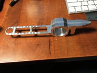
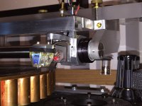
I don’t worry about total weight of the carriage too much though. On my another tonearm, the carriage was weighted 79 g before I installed it. Please see the photos. Someone in UK made it for me. Its 3/4” air bearing is 54 g. The counter weight is 13 g. And, the Audio-Technica head shell is 18 g. The cartridge is 10 g. So, the total is 174 g. It performs wonderfully. What puzzles me is the head shell/carriage I plan to make is almost 80 g from computation of its mass and density. The carriage in the photo is aluminum and its density is higher than carbon fiber and its volume is bigger than the carbon fiber I plan to make, but its mass is only 79 g. I can only guess some where in my calculation was not correct.
It is too later to change the material now. I already ordered the carbon fiber and sent to the maker directly.
Jim
Attachments
Magnetic damping
Hi Jim,
I've been looking at your magnetic damping idea.
I don't think that the position of the magnet relative to the cartridge is going to be a problem. A magnetic field drops in strength pretty quickly with increased distance. The field strength at the cartridges coils, from the damping magnet, will be absolutely miniscule compared to the strength from the cartridges own magnets. Also the magnet and cartridge are held rigidly so there will be no relative movement between the two and therefore no variations in the magnetic field.
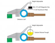
One thing I would change is to align the damping magnet/plate axis tangential to the vertical pivot rather than vertically as it is in your design. In your design the distance between the magnet and plate will change as the arm pivots in the vertical plane. This will cause the level of damping to constantly vary. With the axis tangential to the pivot the level of damping should remain constant.
Niffy
Hi Jim,
I've been looking at your magnetic damping idea.
I don't think that the position of the magnet relative to the cartridge is going to be a problem. A magnetic field drops in strength pretty quickly with increased distance. The field strength at the cartridges coils, from the damping magnet, will be absolutely miniscule compared to the strength from the cartridges own magnets. Also the magnet and cartridge are held rigidly so there will be no relative movement between the two and therefore no variations in the magnetic field.
One thing I would change is to align the damping magnet/plate axis tangential to the vertical pivot rather than vertically as it is in your design. In your design the distance between the magnet and plate will change as the arm pivots in the vertical plane. This will cause the level of damping to constantly vary. With the axis tangential to the pivot the level of damping should remain constant.
Niffy
Edit previous post
I just noticed an error in my previous post.
I wrote "align the damping magnet/plate axis tangential to the vertical pivot". I should have said "align the damping magnet/plate axis radially to the vertical pivot". To clarify the axis that passes through the magnets north and south poles should also pass through the pivot point.
Magnetic damping continued
Hi Jim.
Further to my previous posts regarding magnetic damping.
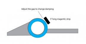
The magnet adjustment is a very good idea. Changing the magnetic gap will change the level of damping. However it will change both the vertical and lateral damping by the same proportion at the same time. The magnet position in your design appears to be arbitrary, is this so? Careful positioning of the magnet gap will allow you to balance the levels of vertical and lateral damping.
If the cartridge body moves laterally by 1mm the magnet will also move relative to the plate by 1mm. If the cartridge body moves vertically by 1mm the amount the magnet will move relative to the plate will be proportional to the ratio between the distance from stylus to pivot to the distance from magnet gap to pivot. If the stylus-pivot distance is equal to the magnet-pivot the ratio will be 1 and a 1mm vertical movement of the cartridge will result in a 1mm movement of the magnet. This will give you the same damping coefficient both vertically and laterally.
However, the lateral effective mass is much higher than the vertical. The same damping coefficient will have less damping effect with the heavier lateral effective mass so the arm would be lightly damped laterally and highly damped vertically (relatively). To get the same damping effect in both planes you would need to make the damping RATIOS the same. I have worked out the formula for this for you and luckily it's a nice simple one.
The pivot-magnet distance should equal the stylus-pivot distance divided by the square root of the ratio between the lateral and vertical effective masses.
Example.
You have a stylus-pivot distance of 89mm.
The lateral effective mass is 190g
The vertical effective mass is 40g.
The effective mass ratio is 4.75
The square root of this is 2.179
89mm divided 2.179
Is 40.8mm.
If you require to have greater damping effect in one plane over the other then the pivot-magnet distance would need to be adjusted. Increasing this distance will increase vertical damping relative to lateral damping and vice versa.
Building an arm that makes this distance adjustable would be difficult and the added complexity would likely have negative effects on sound quality. Some experimentation to find a good balance then build the arm with a fixed distance is probably the best approach.
If you build your arm with the magnet aligned as in my previous posts you will probably find that the magnet gap adjuster will move the magnet forwards and backwards. This will effect tracking force as well as damping. My solution would be to solidly mount the magnet to the carriage and adjust the position of the plate. This has the added advantage that it removes a mechanism from the carriage that could (and therefore probably will) negativity effect sound quality.
I hope this is helpful and not too confusing. I have to admit I struggled a bit trying to word this explanation.
Niffy
Hi Jim.
Further to my previous posts regarding magnetic damping.
The magnet adjustment is a very good idea. Changing the magnetic gap will change the level of damping. However it will change both the vertical and lateral damping by the same proportion at the same time. The magnet position in your design appears to be arbitrary, is this so? Careful positioning of the magnet gap will allow you to balance the levels of vertical and lateral damping.
If the cartridge body moves laterally by 1mm the magnet will also move relative to the plate by 1mm. If the cartridge body moves vertically by 1mm the amount the magnet will move relative to the plate will be proportional to the ratio between the distance from stylus to pivot to the distance from magnet gap to pivot. If the stylus-pivot distance is equal to the magnet-pivot the ratio will be 1 and a 1mm vertical movement of the cartridge will result in a 1mm movement of the magnet. This will give you the same damping coefficient both vertically and laterally.
However, the lateral effective mass is much higher than the vertical. The same damping coefficient will have less damping effect with the heavier lateral effective mass so the arm would be lightly damped laterally and highly damped vertically (relatively). To get the same damping effect in both planes you would need to make the damping RATIOS the same. I have worked out the formula for this for you and luckily it's a nice simple one.
The pivot-magnet distance should equal the stylus-pivot distance divided by the square root of the ratio between the lateral and vertical effective masses.
Example.
You have a stylus-pivot distance of 89mm.
The lateral effective mass is 190g
The vertical effective mass is 40g.
The effective mass ratio is 4.75
The square root of this is 2.179
89mm divided 2.179
Is 40.8mm.
If you require to have greater damping effect in one plane over the other then the pivot-magnet distance would need to be adjusted. Increasing this distance will increase vertical damping relative to lateral damping and vice versa.
Building an arm that makes this distance adjustable would be difficult and the added complexity would likely have negative effects on sound quality. Some experimentation to find a good balance then build the arm with a fixed distance is probably the best approach.
If you build your arm with the magnet aligned as in my previous posts you will probably find that the magnet gap adjuster will move the magnet forwards and backwards. This will effect tracking force as well as damping. My solution would be to solidly mount the magnet to the carriage and adjust the position of the plate. This has the added advantage that it removes a mechanism from the carriage that could (and therefore probably will) negativity effect sound quality.
I hope this is helpful and not too confusing. I have to admit I struggled a bit trying to word this explanation.
Niffy
Hi Niffy,
Yes. I realized that the gap between aluminum plate and magnet will change once the level of LP surface changes.
Actually, I have a better idea but I am not sure if it will work. Please see the drawing. I may utilize the air bearing because air bearing is aluminum. So the gap between the bearing and magnet won’t change.
However, there are still a lot of questions I can’t answer. And, I need to do some experiments if I want to make a Eddy current damping device. I decide to give up Eddy current damping device and just make a silicone one although silicone damping device is kind of messy.
Jim
Attachments
Hi Jim,
I think both damping systems have their strengths. I had the pleasure of living with a Townsend rock reference with Excalibur arm for a while. I was never happy about having exposed silicon fluid that close to my precious vinyl. Even though the deck lived under its dust cover the silicon fluid ended up looking like porridge. Although the trough was easy to remove from the deck removing the fluid from the trough wasn't. It was impossible not to get some on the outside of the trough and then near impossible to remove it from there. The possibility of transferring some to a record whilst changing seemed a bit high. In the electroplating industry if a component is contaminated with only a small amount it is impossible to then plate. The component has to be sand blasted or thrown away. It's that difficult to fully remove.
I prefer your original magnetic damping layout. In the design in the previous post the cartridge moves relative to the magnet and the magnet will have to be much stronger overall. The chances of interraction are quite high.
I haven't fully explored both systems but get the feeling that magnetic might be better if low levels of damping are required and silicon better for higher levels.
Niffy
Tungten carbide joy
Hi all,
I've been busy since my last post building and testing a new rail using the tungsten carbide rods graciously donated by hottattoo. I have undertaken all the tests using the same wheels and bearings as used in the previous tests, homemade pin bearings and 15.5mm diameter stainless steel wheels with 0.15mm radius edges. The rods were highly polished using diamond lapping compound to a finish of 0.5micron, so smooth they feel slippery. Yet still not quite as smooth as the glass rods. One of the rods had a deep helical score along it length, an artefact of the grinding process. This took for ever to polish out.
These rods are really dense. The entire rail structure weighs half as much again as the identical rail with glass rods. The rail support structure is very rigid and well damped, the stiffness of the tungsten rods will have increased the rigidity of the entire structure considerably.
With glass rods this design achieved a lateral coefficient of friction of 0.0035. With the tungsten carbide rods this figure dropped to 0.0028. That's an amazing 20% reduction. I really hadn't expected anywhere near that level of improvement. At hottattoo's request I did test the rods before they were polished. The finish looked like it had been finished with about a 800grit sanding paper. Even in this rougher finish they still outperformed the glass rods with a mean coefficient of friction of 0.0030. As expected the polished rods were also quieter when the test carriage was rolled back and forth compared to the unpolished, about the same as with the glass rods maybe a little bit noisier. A simple pendulum test indicates that vertical friction is also reduced, probably by 10%.
I have not yet fitted this rail to the deck so how this translates into sound quality is as yet a completely unknown. I have more tests to perform before I do fit it.
When I changed the wheel material from aluminium to much harder stainless steel lateral friction dropped by 23% and when I swapped from glass rods to tungsten carbide it dropped by a further 20%. It seems obvious that changing the material from which I make the wheels to something much harder again should further reduce friction. To this end I have been researching alternative materials. Unfortunately the best candidates are simply not available in the quantity or form that I require. I have managed to find and purchase, at a high price, a small sheet of grade 5 titanium alloy, the aerospace stuff. It's considerably harder than the 304 stainless that I'm currently using but not as hard as the 440C stainless that I hoped to find. Then today I made a lucky find. When googling tungsten carbide most of the returns are for tungsten carbide jewellery. It seems fashionable to turn high tech materials into jewellery. Titanium, carbon fibre and ceramic rings abound. Amongst all of this I found some tungsten carbide rings in American size 2. For the men among us who know nothing of ring sizes, size 2 is TINY, 13.2mmID, and very uncommon. It wouldn't even fit over the tip of my little finger. The ring is also only 2mm wide with an OD of about 16mm. Almost exactly the size I need. So I purchased 2 at great expense, £3 each. My plan is to make titanium wheels with the tungsten carbide rings as tyres. Tungsten Carbide on tungsten carbide should give the lowest possible rolling resistance. Also, the coefficient of friction between two pieces of tungsten carbide is about half that of tungsten carbide to steel. The shape of the rings outer surface would have increased vertical friction by about 50% but the reduced coefficient of friction will bring it back down to a level that will probably be lower than it is at the moment. My only fear is that the rings are not perfectly round.
Unfortunately all of the new materials are coming from China or the States so it will be a while before they arrive. I'm postponing making the new bearings using the tungsten carbide pivots and sapphire vees until I've tested the new materials. I don't want to be swapping them out too often, I want to find the best option and fit them once. I will of course keep you posted as to the results.
Niffy.
Hi Niffy,
You have been VERY busy !!! Thanks for all your time, hard work, and very detailed report on the progress of this tonearm concept. I think once and for all, we will see the true capabilities of this mechanical arm. I am very happy to have made a small contribution to this project. It is people like you, Jim and others who have contributed greatly to the DIY community.
You may want to try using a skeletonized inner wheel of carbon fiber, teflon, delrin etc. depending on weather you will use the inner wheel material as a direct part of the bearing or insert a different material for supporting the axle, just to keep the wheel weight down. Just my 2 cents.
It will be a real challenge to keep the entire wheel assembly concentric, given the 2 or 3 parts making up the completed wheel.
Keep up the good work and please supply some detailed pictures of your design progress. The world is watching !!!!
Joe
- Home
- Source & Line
- Analogue Source
- DIY linear tonearm