Could be a bias problem, if not:
T10 and T11 need a 220pf from collector to base to slow them down.
I had the same problem in a quasi design that had similar drivers.
T10 and T11 need a 220pf from collector to base to slow them down.
I had the same problem in a quasi design that had similar drivers.
Could be a bias problem, if not:
T10 and T11 need a 220pf from collector to base to slow them down.
I had the same problem in a quasi design that had similar drivers.
Are you shure of T10 and T11?What about T8 and T9?
Are you shure of T10 and T11?What about T8 and T9?
Try t10 and 11 first.
It's the same like AKSA is suggesting in post 10 http://www.diyaudio.com/forums/solid-state/27200-hexfet-power-amplifier.html
I'm gonna try this in the original design of the hexfet amp without the other mods but will add a 0,47Ohm resistor over the fuses.
I'm gonna try this in the original design of the hexfet amp without the other mods but will add a 0,47Ohm resistor over the fuses.
blowing some life in this thread I also have the IGBT version and only one is playing without any probs but I was wondering if I could change the IGBT's with IRF240-9240 fets?
Hi. I have built this amp and noticed it has a problem of thermal drift. If you assemble the amp with no mistakes, incorperating the few mods added at a later date by Elektor it sounds great, but over time a DC voltage is meauresable at the output to the speaker. I studied the cause of this thermal drift and designed a pcb that thermally couples T1 T2 and T3 T4 together as suggested by Elektor, plus I coupled D1 D2 T5 T6 together. This appears to have cured the problem of maintaining the connection between T12 and T13 to within a few mV of zero. Great care was taken to keep the layout of the pcb as symetrical as the circuit. The result is a very stable and tidy amp that is well worth building.
I think meanman 1964 should read and understand the content of my letter befor passing an opinion. I am aware that the T5 D1 are thermally coupled as are T6 D2. My letter is meant to imply that the revised PCB layout thermally couples all 4 devices together. This conclusion was reached after watching the DC voltage at the output drift when applying the warmth of a finger to either T5 or T6.
I think meanman 1964 should read and understand the content of my letter befor passing an opinion. I am aware that the T5 D1 are thermally coupled as are T6 D2. My letter is meant to imply that the revised PCB layout thermally couples all 4 devices together. This conclusion was reached after watching the DC voltage at the output drift when applying the warmth of a finger to either T5 or T6.
Sorry not my itention.Can you give me the layout of your board.I've a few amps with probs?Are they still working well?
I think meanman 1964 should read and understand the content of my letter befor passing an opinion. I am aware that the T5 D1 are thermally coupled as are T6 D2. My letter is meant to imply that the revised PCB layout thermally couples all 4 devices together. This conclusion was reached after watching the DC voltage at the output drift when applying the warmth of a finger to either T5 or T6.
can you post the new pcb layout to reconstruct it.
egberttheone thanks alot i will mke this modifications or rebuild it all and then tell you the result .... you were very supporting to me 🙂 thank you
Last edited:
So I typed "Giesberts HEXFET AMP" into google and guess what !? I got lots of hits with the same problem. The weird thing is that some blame that it does work; and other say it needs modification(s), then some one says that I need to place 100N in parallel with R30 & R31 to prevent it from oscillating. Because the resistors will work like a coil.
Sorry for my bad English.
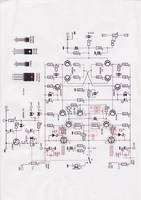
On your original circuit diagram T10 and T11 need a 120pf capacitor from collector to base.
I designed a very similar amp and that oscillated badly until I fitted those two capacitors.
ELEKTOR HEXFET AMPLIFIER IRF540 IRF9540
The elektor hexfet without any modification.
For more datails please look.hexfet amplifier - YouTube
power hexfet amplifier - YouTube
POWER AMPLIFIER HEXFET SPECIFICATIONS - YouTube
The elektor hexfet without any modification.
For more datails please look.hexfet amplifier - YouTube
power hexfet amplifier - YouTube
POWER AMPLIFIER HEXFET SPECIFICATIONS - YouTube
Attachments
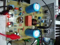
Judging by what I see there are some changes such as lack of 2 fuses but then there are four elements that seem SMT plus some resistors in series or parallel series perhaps to reach the correct value. the other is not in fact I even when I built this amplifier one of two plates worked great while.
- Status
- Not open for further replies.
- Home
- Amplifiers
- Solid State
- [DIY] HEXFET AMP total disaster?