Solution if probe calibrated.
You could temporarly disconnect the hot side from C2.
After all, the four passives (besides the nulling circuit part)
on the input make up a ... filter 🙂
This will clean up the measurements. I for one would like to
see the new pics.
You could temporarly disconnect the hot side from C2.
After all, the four passives (besides the nulling circuit part)
on the input make up a ... filter 🙂
This will clean up the measurements. I for one would like to
see the new pics.
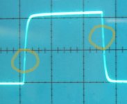
So I ones found some time and courage again to restore the project again, I have now some good PCB caps installed (C11 & C12). I re checked all the connections(earthing) and calibration of the oscilloscope, probes and the oscillator. This is the result:
20khz 10vpp
I did a try decreasing C5 and R5 but it does not give a better result infect worse. What can I do to improve things? 😎
(All the ballast's capacitor, resistor does almost not affect the output what so ever, only the capacitor gives a small ripple at the peaks)
20khz 10vpp
An externally hosted image should be here but it was not working when we last tested it.
I did a try decreasing C5 and R5 but it does not give a better result infect worse. What can I do to improve things? 😎
(All the ballast's capacitor, resistor does almost not affect the output what so ever, only the capacitor gives a small ripple at the peaks)
The squarewave itself looks "perfect", but the problem lies within the details... The amplifier shows instability/crossover when slewing, typically caused by too big feedbackcap. This is not your job, it's the designers job.
But, only listening can tell you if amp works fine... Attach speaker and listen !
Mike
But, only listening can tell you if amp works fine... Attach speaker and listen !
Mike
Attachments
Is C2 disconnected temporarly in the picture of post 42?
A visible input signal as in the other pictures is helpfull
A visible input signal as in the other pictures is helpfull
The amplifier sound amazingly bright 🙂 Try-ing to improve things is just for hobby and getting more understanding of amplifiers. I did some compare tests with other designs from elector and this one beats it all. BTW I cant see the thing you show on the picture on the scoop, but there is a little misinforming when connected with a resistor or capacitor, but compared with other amplifiers its very limited.
Edit:
No, it seems that its nearly imposible to show the input and output because of the earthing, it is deforming or the input measurement; or the output measurement. I first measured the input signal it is perfectly square wave. The i put the probe on the output (and placed the earth to the speaker earth this way i get fair measurements)
Edit:
rtirion said:Is C2 disconnected temporarly in the picture of post 42?
A visible input signal as in the other pictures is helpfull
No, it seems that its nearly imposible to show the input and output because of the earthing, it is deforming or the input measurement; or the output measurement. I first measured the input signal it is perfectly square wave. The i put the probe on the output (and placed the earth to the speaker earth this way i get fair measurements)
... better square wave. Why?
Hmm..
Checking for stability, slewing and such.
Maybe a little important. Wouldn't you agree?
Last try:
I don't understand what the problem is to disconnect the hot side
from C2.
This way you make sure the input filter does not mok up your
measurements.
If you get this measurement right, you will be able to tweak
the compensation just right.
btw your comment:
That's good. But...
It could be the amp is overcompensated now. That's what the
measurement is for.
Especially when you did not perform all the proposed (required)
modifications.
Or...
If you are happy with the amp as it is now, leave it this way.
I would not be satisfied. Maybe I take this amp stuff to serious.
Regards
Hmm..
Checking for stability, slewing and such.
Maybe a little important. Wouldn't you agree?
Last try:
I don't understand what the problem is to disconnect the hot side
from C2.
This way you make sure the input filter does not mok up your
measurements.
If you get this measurement right, you will be able to tweak
the compensation just right.
btw your comment:
indicates that you no longer have stability problems.(All the ballast's capacitor, resistor does almost not affect the output what so ever, only the capacitor gives a small ripple at the peaks)
That's good. But...
It could be the amp is overcompensated now. That's what the
measurement is for.
Especially when you did not perform all the proposed (required)
modifications.
Or...
If you are happy with the amp as it is now, leave it this way.
I would not be satisfied. Maybe I take this amp stuff to serious.
Regards
Okey sorry for the kick but if people search for a solution to the problems with this amp they would be disappointed if they try the things above! The amp still dint seems to be stable, its works well but some time it just start oscillating and blows out the IRF's. So I made the same modification + extras mentioned above. The total modification:
It plays for 2 weeks now without a problem but still, I can not guarantee that it will maintain stable. A other problem showed up I got a awesome hum ming sound(ground loop). It took me some time to figure out what was causing it, I made this modification:
Hope that I can help people who gave up hope!
😀
An externally hosted image should be here but it was not working when we last tested it.
It plays for 2 weeks now without a problem but still, I can not guarantee that it will maintain stable. A other problem showed up I got a awesome hum ming sound(ground loop). It took me some time to figure out what was causing it, I made this modification:
An externally hosted image should be here but it was not working when we last tested it.
Hope that I can help people who gave up hope!
😀
No IRFP9140 and IRFP240 is a pair, see also data sheets found in google. I was wondering the ground like I connected it does remove the hum for me but would it maybe make bad influence? There will be running current trough the speaker ground. 
I personaly think you better not connect the input-ground together with the output ground because of a ground-loop.
You will not have a ground loop thats why you need to cut the bridge, the input capacitors, will be on the input side ground.
I'm not thinking that, its a consideration. When current walk trough the speaker ground; the input ground will be pulled up & down. just a thought... 🙄
it is possible to set the current higher; but if it will improve things ? The new fets are capable of dissipating 3 times more heat then the old ones about 150Watts. The amplifier will possibly be capable of driving lower impedance speakers as well(if your power supply is calculated on that). 😀
it is possible to set the current higher; but if it will improve things ? The new fets are capable of dissipating 3 times more heat then the old ones about 150Watts. The amplifier will possibly be capable of driving lower impedance speakers as well(if your power supply is calculated on that). 😀
Is it still working stable?
The amplifier works stable although I did not yet take it into service because it’s still not finished. I earlier posted a reply about earth loops and how to solve this by cutting a bridge, well I got rid of this plan because I got some stability problems witch where solved by reconnecting the bridge. I now use the INA134 line receiver from burr brown, now I do not have any hum or noise any more. I’m still assembling the whole monster machine together, it is REALY big. 😱
- Status
- Not open for further replies.
- Home
- Amplifiers
- Solid State
- [DIY] HEXFET AMP total disaster?