If you mean the MPC-5 (emiter resistor)look at this site
http://www.thel-audioworld.de/bauteile/mox/mox.htm
http://www.thel-audioworld.de/bauteile/mox/mox.htm
It would be suitable if the value of what I need was available. Should the "MOX-5" make any inductance? it is not wirewounded I think I order a pair of these. Thanks for the link! 😀
I found some old resistors, they rated 2W instead of 5W, but good enough for testing this are metal oxide one's. So replaced R31 & R30 removed the 100N modification. No luck the circuit again goes oscillating. Increasing R29 & R26 to 120 ohms gives no luck ether. The caps over R31 & R30 works perfect. in no situation it start oscillating again. 
So I was going to test the circuit, I calibrated my CR oscillator(AG-203 Trio) It gives perfectly square and sinus waves. But ones connected to the circuit the square gets rounded edges, If power is applied to the circuit it gets very distorted. Why is this happening? I have all earthing correct, even with the probe directly on the output of the oscillator it is misformed by the circuit. Any advice? its output is 600ohms. 😕
So I was going to test the circuit, I calibrated my CR oscillator(AG-203 Trio) It gives perfectly square and sinus waves. But ones connected to the circuit the square gets rounded edges, If power is applied to the circuit it gets very distorted. Why is this happening? I have all earthing correct, even with the probe directly on the output of the oscillator it is misformed by the circuit. Any advice? its output is 600ohms. 😕
Hexfet / Igbt
Elektuur published an article in 2002 dealing with the sibling
of this amp called something like IGBT Amplifier.
This unit suffered from similar instability issues.
The cap on R31 is just one part of the solution.
NO cap on R30 though otherwise you will severly hamper the
proper operation of the amp. You probably noticed the bandwith
limiting / slewing with the 100n, did you?
I.e 100n is not the proper value!
I will provide you this article, on the condition you absolutly do
not redistribute it. Not on this forum, or otherwise.
Drop me a mail (dutch is just fine) if you are interested.
Hè ritrion
The solution what you mean is that from halfgeleidergids 2002?
Isn't that not only for the IGBT version of the amp?
Could you use it for the Hexfet as well?And what about the resistors for T8 and T9 wich must be soldered between collector and ground?
The solution what you mean is that from halfgeleidergids 2002?
Isn't that not only for the IGBT version of the amp?
Could you use it for the Hexfet as well?And what about the resistors for T8 and T9 wich must be soldered between collector and ground?
solution
Solution works for both. In my experience.
CFP is a source of oscillation. So that's the reason for the
resistors of 20k to ground coming from the collectors.
My original HEXFET was an oscillator, not an amp🙂
At the time, I did add capacitance to the feedback resistor in the
output stage. And changed the compensation caps in the diff pair.
This was all changed again, after the elektuur update in 2002.
Proper bias setting after the changes is mandatory.
Offset nulling, same story.
Both settings interact a little.
Placing 20kohms resistors from collector T8 & T9 to the ground improves stability, placing 27N over R31 makes it even more stable. This modification does not effect the output results what so ever. C8 & C9 really need to be placed on the PCB, placing only the power supply capacitors is not enough without these capacitors placed, the results are poor and some times the thing starts oscillating even with the modifications (as mentioned above) done. Amplifier seems to work flawlessly now. If every thing is assembled in to its case I will do some testing. 
3 things to change to get it work(stopping it from oscillating and instability):
- Add a 27N capacitor in parallel with R31.
- Add Resistor from T8 collector to the ground/earth.
- Add Resistor from T9 collector to the ground/earth.
You can place these components on the backside of the PCB, The other components are original from the schematic drawings.
Besure to use some good caps for C11 & C12, some low ESR types will definitely improve performance.

It works for al twelve I made, they run great now.
Oeps by C8 & C9 i meant C11 & C12
- Add a 27N capacitor in parallel with R31.
- Add Resistor from T8 collector to the ground/earth.
- Add Resistor from T9 collector to the ground/earth.
You can place these components on the backside of the PCB, The other components are original from the schematic drawings.
Besure to use some good caps for C11 & C12, some low ESR types will definitely improve performance.
It works for al twelve I made, they run great now.
egberttheone said:Placing 20kohms resistors from collector T8 & T9 to the ground improves stability, placing 27N over R31 makes it even more stable. This modification does not effect the output results what so ever. C8 & C9 really need to be placed on the PCB, placing only the power supply capacitors is not enough without these capacitors placed, the results are poor and some times the thing starts oscillating even with the modifications (as mentioned above) done. Amplifier seems to work flawlessly now. If every thing is assembled in to its case I will do some testing.
Oeps by C8 & C9 i meant C11 & C12
It works for al twelve I made, they run great now.
Hmm...
I have some serious doubts...
You could show us a picture of the leading edge from a
10V 10 or 15 Khz square. In a resistive load for pic 1.
With a resistive load and 2uF parallel for pic 2.
I think by loading the CFP driver stage with the resistors to
ground, you would like some extra current coming of the
diff pair which is fed by the CCS.
This, at least, will be true for higher frequencys. As you
know at a higher frequency the prveious stage gets loaded quit
a bit more. Lower impedance due to 1 / (omega*C), where
omega equals 2*pi*f.
I would like to ask for proper testing of a single channel, before
changing all the other channels.
For instance, when you do the reactive load test, use bursts. Not
a contiuous signal.
There is more, but nuff said...
from meanman1964:
Have you seen this amp http://users.otenet.gr/~athsam/powe..._hexfet_eng.htm
Nice copy from elektuur/ elektor. Same circuit, and guess what?
Same problems. Sam, the COPIER, did bother to mention elektor.
However, I doubt he has written concent from the elektor people.
Sad. :-(
rtirion,
I understand copyright issues of the Elektor update, but since there are quite a few of us who have multiple boards of this oscillator/amp (I have 4 fully assembled and 2 partially populated), would you be kind enough to let us know where to begin, in order to tame this amp. I had a pair playing for a few weeks, before they blew the output stage and they sounded quite good - almost a valve like sound.
If the article is in English, may I please have a copy.
Thanks a lot.
Sam,
The article is in Dutch. But I found a copy in English as well.
The English copy contains a mistake.
Send me an email, through this forum, with your e-mail address
and I will provide you this including a correction.
This:
still holds.
The article is in Dutch. But I found a copy in English as well.
The English copy contains a mistake.
Send me an email, through this forum, with your e-mail address
and I will provide you this including a correction.
This:
I will provide you this article, on the condition you absolutly do not redistribute it. Not on this forum, or otherwise.
still holds.
ok i did some stability tests keep in mind that i have some cheap caps used to test the module, soon i will place low ESR types on the boards. It does not have a proper casing, cables are 0,75mm2. The resistor load is free from induction.
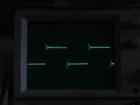
The images with two lines, the upper line is the output the lower line is the input (it has a slight bend because of the capacitive load from the input of the amplifier)
All images are clickable.
This is the output if you don't have assembled C11 & C12 assembled. 20khz 10vpp 4ohm speaker load.
This is the output with the caps C11 & C12 assembled. 20khz 10vpp 4ohm speaker load.
This is the output with a capacitive load of 1,2uf. 20khz 10vpp
This is the output with a resistor load of 1 ohm. 20khz 10vpp. It draws almost 150Watt from the mains.
This is the output with a resistor load of 4 ohm. 20khz 10vpp.
This is the output with a resistor load of 4 ohm and a 1,2uf capacitive load in serie. 20khz 10vpp.
This is the output with a resistor load of 4 ohm. 30khz 10vpp.
The images with two lines, the upper line is the output the lower line is the input (it has a slight bend because of the capacitive load from the input of the amplifier)
All images are clickable.
An externally hosted image should be here but it was not working when we last tested it.
This is the output if you don't have assembled C11 & C12 assembled. 20khz 10vpp 4ohm speaker load.
An externally hosted image should be here but it was not working when we last tested it.
This is the output with the caps C11 & C12 assembled. 20khz 10vpp 4ohm speaker load.
An externally hosted image should be here but it was not working when we last tested it.
This is the output with a capacitive load of 1,2uf. 20khz 10vpp
An externally hosted image should be here but it was not working when we last tested it.
This is the output with a resistor load of 1 ohm. 20khz 10vpp. It draws almost 150Watt from the mains.
An externally hosted image should be here but it was not working when we last tested it.
This is the output with a resistor load of 4 ohm. 20khz 10vpp.
An externally hosted image should be here but it was not working when we last tested it.
This is the output with a resistor load of 4 ohm and a 1,2uf capacitive load in serie. 20khz 10vpp.
An externally hosted image should be here but it was not working when we last tested it.
This is the output with a resistor load of 4 ohm. 30khz 10vpp.
Hmm, practically all scope shots show temporaly oscillation when slewing. Thats likely to sound extreme bright. (only conditionally stable)
You might consider reducing c5, until the amp starts to overshoot.
I would say, that amp is definitely not correctly fb-compensated.
Mike
You might consider reducing c5, until the amp starts to overshoot.
I would say, that amp is definitely not correctly fb-compensated.
Mike
Probe Calibration
To get a better view, it would be nice if you calibrate the probe
of your scope.
Referencing the last picture:
The lower trace shows the input signal. That only resembles a
square. Top of leading edge is rounded off, bottom trailing edge...
The upper trace the shows the output signal. Garbage in...
This way it's to difficult to draw any conclusion.
Looking at the pics, I would say sub-obtimal compensation.
Slewing problems, etc...
In all, I should urge you to look at my previous recommendation.

Nice tek
btw Your tek 2246 has a perfect calibration point.
Should you require a little extra info on the cal proccess give
me a holler.
btw Your tek 2246 has a perfect calibration point.
Should you require a little extra info on the cal proccess give
me a holler.
Okey this is a misunderstanding, I got the probe calibrated on the calibration point, if I put the probe on the rc oscillator it gives a very nice square wave but, if I connect the rc oscillator to the amp, the load thus the amp is misinforming the square wave I guess because of its capacitive load is there any way to improve performance? 
- Status
- Not open for further replies.
- Home
- Amplifiers
- Solid State
- [DIY] HEXFET AMP total disaster?