Hello, I started building a amplifier some time ago. I wanted a simple design what would works stable and will perform very good. I decided to go with a working design from a electronics book.
After some reading and searching I found "Giesberts HEXFET AMP" the best to go with. I trusted blindly that the design will perform like described so I made 12(!!) PCB's right away. Now that they all where build up.
I was going to test a module so I toke some crocodile wires and connected the module up to my labpower supply and turned it on. I draw the maximum current to 0,5 amps and the voltage to 10 Volts. The led from current limitting directly started lighting?? Thats weird. Turned the power off and checked and rechecked all the components en connections. Every thing was just fine.
So I typed "Giesberts HEXFET AMP" into google and guess what !? I got lots of hits with the same problem. The weird thing is that some blame that it does work; and other say it needs modification(s), then some one says that I need to place 100N in parallel with R30 & R31 to prevent it from oscillating. Because the resistors will work like a coil.
I did this but no difference. The amp runs fine on symmetric 5V but if I put it higher the current rises explosively and the fets run red hot . I also removed the fuses from the sockets and put on the power, @ about 15Vs the resistors R22 & R23 starts smoking. Thats also strains, no speaker connected, mosfets disconnected from the power supply and still things start smoking. PLEASE HELP ?
  I don't know where to start, I have a oscilloscope and dual labpowersupply.
I found a thread in this form and carefully read it, I tryed to increase R26&R29 but also no difference!
Here is the link to the thread : Click
About assembly: I did not pair the transistors bc550 and bc560 could this infect the stability? (I did thermally pair them with a piece of copper but did no pair the characteristics)
Here is the schematic:
Sorry for my bad English.
After some reading and searching I found "Giesberts HEXFET AMP" the best to go with. I trusted blindly that the design will perform like described so I made 12(!!) PCB's right away. Now that they all where build up.
I was going to test a module so I toke some crocodile wires and connected the module up to my labpower supply and turned it on. I draw the maximum current to 0,5 amps and the voltage to 10 Volts. The led from current limitting directly started lighting??
Thats weird. Turned the power off and checked and rechecked all the components en connections. Every thing was just fine. So I typed "Giesberts HEXFET AMP" into google and guess what !? I got lots of hits with the same problem. The weird thing is that some blame that it does work; and other say it needs modification(s), then some one says that I need to place 100N in parallel with R30 & R31 to prevent it from oscillating. Because the resistors will work like a coil.
I did this but no difference. The amp runs fine on symmetric 5V but if I put it higher the current rises explosively and the fets run red hot
. I also removed the fuses from the sockets and put on the power, @ about 15Vs the resistors R22 & R23 starts smoking. Thats also strains, no speaker connected, mosfets disconnected from the power supply and still things start smoking. PLEASE HELP ? I don't know where to start, I have a oscilloscope and dual labpowersupply.I found a thread in this form and carefully read it, I tryed to increase R26&R29 but also no difference!
Here is the link to the thread : Click
About assembly: I did not pair the transistors bc550 and bc560 could this infect the stability? (I did thermally pair them with a piece of copper but did no pair the characteristics)
Here is the schematic:
An externally hosted image should be here but it was not working when we last tested it.
Sorry for my bad English.
I built 6 of these almost 10 years ago and cannot recall any serious problems, except for it being pretty sensitive to hum (low PSRR). Also, they seemed to have a rather harsh top end. They cost pretty much nothing and were quite reliable (I think the're still running!) I didn't do any matching of anything, neither did I try and thermally couple them. In other words, I didn't do anything fancy or special at all.
I'm thinking there must be something wrong with your bias circuit around T7. When you connect your scope to the output, does it latch to a rail or does it stay at 0V?
Cheers
Gert
I'm thinking there must be something wrong with your bias circuit around T7. When you connect your scope to the output, does it latch to a rail or does it stay at 0V?
Cheers
Gert
astouffer said:If R22 and R23 are smoking then the transistors are either oscillating or conducting full. See what voltage you get at the base of each one and try hooking the scope up also. Not sure what else could be causing it, maybe an error with the PCB or bad layout.
I agree.
It verifies that the BD140/141 have not burnt..
try you to disconnect the base of these.
later check the base signal from T1 and T3.
There is perhaps some problem on the differential amplifiers.
bye
")
I remember this IRF540 / 9540 HEXFET from Elektor magazine.
The output drivers T10 T11 and output transistors T12 T13
has a voltage gain of 2-3. Gain ~= (150+68)/68
There is a local feedback in this stage using R31 R30 to set this gain.
The problem is you have no capacitance to compensate
and so make this local feedback amplifier stage STABLE.
These HEXFET like most MOSFET are very fast, compared to normal BJT Power transistors.
The usual way, as you mention, to put a cap in parallel with R31
may not work as well in this type of Current, Emitter, Feedback configuration.
The same problem can sometimes happen in Complementary Fold-Back darlington configuration.
In this case we can say we have two CFB in push pull. With some resistors to reduce gain.
When emitter feedback is used ( R31 is providing feedback current to EMITTERS of BD139 BD140 )
you will have to try to break this oscillation loop
using the slow down fiter capacitors in some other place.
------------------
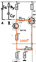
What we have to play with is the loop ( I only speak of the upper part now):
R31 - R25 - T10 - R26 - T12 - R31
See my attached part of schematic.
Somewhere where is best place, we have to put a compensation, slow down, capacitance.
See alternative A. in my drawing.
The usual way is to put a cap across R24. Cap Cx.
I would try a cap with value:
1nF ... 22nF
Of course you would put same value cap in the lower half of amplifier
.. cap across R27
The procedure is the following.
1. Begin with the higher value caps, 22nF
2. If amplifier is stable, take the nest lower 50% value = 10nF
3. If still stable take next = 4.7nF
Repeat this until amplfier is no longer stable.
Say it starts oscillate again at 2.2nF.
And is stable at 4.7nF.
Then I would, to have a safety margin, use 6.8nF for these compensation caps.
Don't forget to add same value cap
across BOTH R24 and R27.
---------------
The optimal way to compensate is to use alternative B. in my drawing.
Ry can be maybe 2.2 Ohm - 22 Ohm
and the cap Cy same as in alternative A. .. 1nF - 22nF
To determine the optimal values we would use oscilloscope
and adjust for best possible looking squarewave.

If I am sure this will work for your amplifier project?
The truth is ----- I AM NOT SURE.
I have to put in a disclaimer, isn't this what they call it.
But
the method I describe is the way I have seen used
in other same type of amplifier stages.
lineup
The output drivers T10 T11 and output transistors T12 T13
has a voltage gain of 2-3. Gain ~= (150+68)/68
There is a local feedback in this stage using R31 R30 to set this gain.
The problem is you have no capacitance to compensate
and so make this local feedback amplifier stage STABLE.
These HEXFET like most MOSFET are very fast, compared to normal BJT Power transistors.
The usual way, as you mention, to put a cap in parallel with R31
may not work as well in this type of Current, Emitter, Feedback configuration.
The same problem can sometimes happen in Complementary Fold-Back darlington configuration.
In this case we can say we have two CFB in push pull. With some resistors to reduce gain.
When emitter feedback is used ( R31 is providing feedback current to EMITTERS of BD139 BD140 )
you will have to try to break this oscillation loop
using the slow down fiter capacitors in some other place.
------------------
What we have to play with is the loop ( I only speak of the upper part now):
R31 - R25 - T10 - R26 - T12 - R31
See my attached part of schematic.
Somewhere where is best place, we have to put a compensation, slow down, capacitance.
See alternative A. in my drawing.
The usual way is to put a cap across R24. Cap Cx.
I would try a cap with value:
1nF ... 22nF
Of course you would put same value cap in the lower half of amplifier
.. cap across R27
The procedure is the following.
1. Begin with the higher value caps, 22nF
2. If amplifier is stable, take the nest lower 50% value = 10nF
3. If still stable take next = 4.7nF
Repeat this until amplfier is no longer stable.
Say it starts oscillate again at 2.2nF.
And is stable at 4.7nF.
Then I would, to have a safety margin, use 6.8nF for these compensation caps.
Don't forget to add same value cap
across BOTH R24 and R27.
---------------
The optimal way to compensate is to use alternative B. in my drawing.
Ry can be maybe 2.2 Ohm - 22 Ohm
and the cap Cy same as in alternative A. .. 1nF - 22nF
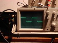
To determine the optimal values we would use oscilloscope
and adjust for best possible looking squarewave.
If I am sure this will work for your amplifier project?
The truth is ----- I AM NOT SURE.
I have to put in a disclaimer, isn't this what they call it.
But
the method I describe is the way I have seen used
in other same type of amplifier stages.
lineup
Attachments
Thanks for the replys! i'm going to get it work without the fets in the first place.
the link to the circuit diagram is broken so here it is agian:
the link to the circuit diagram is broken so here it is agian:
An externally hosted image should be here but it was not working when we last tested it.
Okey, I found the problem, I pulled the fuses. Resistor R22 and R23 runs hot. the only thing that can cause this is:
-T8,T9 or T7 defect
-T3,T1 defect, or wrong type.
-T6 or T5 defect or wrong type.
Then I found out that T6 and T5 runs a little warm, that is strange because it only needs to produce a steady 3ma current. Then I found out the most stupid mistake! I putted the leds in wrong polarization! After I turned them around, the circuits runs alive. putted the fuses to there place, but the current again raised like hell, on 7,5V symmetric it runs a 200ma. Putted the scoop to T10 collector and saw a huge oscillation there. Putted caps in parallel with R30 & R31 guess, it works! putting the caps resolves all the problems with this circuit. It runs just great now, I let you guys know if al the other 14 will work to.
if T8 & T9 runs hot that is because they oscillate! Modify the circuit by adding, 100N caps in parallel with R30 & R31 I put them on the bottom of the circuit right beneed the R30 & R31. Why did elektor has this problems? because they didn't use this type of resistors. The resistors I used and other members work like a coil and making some inductance.
Hi egberttheone
You should try to change the value of the gate resistors to the following values:
R26 change to 120 Ohms
R29 change to 180 Ohms
Try to change the values of the Zobel network R32 R33 and C10.
Try to increase the value of the R3 and R4
IMPORTANT:
Connect a 1N4004 or similar and a 12V zener protection diodes to Gate-Source terminals of each mosfet.
The compensation you have made is an emergency solution that result in a poor behavior of the amp at high frequencies.
Regards
Vittorio
With increasing resistance in the Zobel network,
from originaly 3,4ohms to 11ohms, I got them very stable,
no ringing, no overshoot,.... and very good sound
....without changing gate stoper,...
.....R30 and R31 inductive, or not, it is stable, I was tried...
.... and no extra pole
from originaly 3,4ohms to 11ohms, I got them very stable,
no ringing, no overshoot,.... and very good sound
....without changing gate stoper,...
.....R30 and R31 inductive, or not, it is stable, I was tried...
.... and no extra pole
Attachments
Radule,
For stability check, in a power amp is not enough to measure only on resistive load.
You should try to measure also on reactive(capacitive) load.
As an example,4 Ohms series with 470 nF or a pure capacitive 470 nF/ 1 uF freq.1 kHz and/or 10 kHz.
Please I pray you to put on the site the results of the measurements.
Thank you
Vittorio
I will test the amplifier, but the audio generator I use does not produce nice square waves so I first need to calibrate the unit. Why use a capacitive load? most amplifiers wont survive doing that why is this useful to test any way? because the load that will be on is inductive. I will test a resistor load (4ohm) and capacitive/resistor serie load. I did some small testing and all responses look quite good.
I would like to have some powerfilm resistors(non-inductive), to replace the wirewound ones but couldn't find a reseller for this. Any one knows where to get these resistors?
I would like to have some powerfilm resistors(non-inductive), to replace the wirewound ones but couldn't find a reseller for this. Any one knows where to get these resistors?
- Status
- This old topic is closed. If you want to reopen this topic, contact a moderator using the "Report Post" button.
- Home
- Amplifiers
- Solid State
- [DIY] HEXFET AMP total disaster?