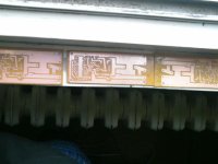
Yes,it's good,if you hear distortion,change output inductor,when I use green toroid it have much distortion and when change to yelow toroid,I don't hear distortion.
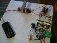
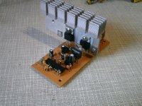
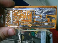
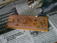
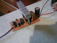
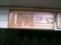
I completed amp with SG,check pictures
It's very small and tiny 😀
And cheap too (for forum I'll make version with SG3524 because it's much cheaper. 😀
I completed amp with SG,check pictures
It's very small and tiny 😀
And cheap too (for forum I'll make version with SG3524 because it's much cheaper. 😀
Attachments
-
 PTDC0017.JPG53.8 KB · Views: 1,144
 -
 PTDC00011.JPG66.8 KB · Views: 331
 -
 PTDC0028.JPG98.3 KB · Views: 429
 -
 PTDC0027.JPG95.7 KB · Views: 447
 -
 PTDC0025.JPG79.1 KB · Views: 368
 -
 PTDC0023.JPG82 KB · Views: 1,051
 -
 PTDC00021.JPG69 KB · Views: 1,073
 -
 PTDC0020.JPG43.6 KB · Views: 1,099
 -
 PTDC0018.JPG49.3 KB · Views: 1,115
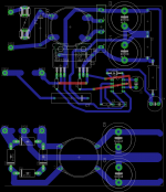
Try to use shorter lines.
I don't have internet to attach here,I maked class d amp with Sg3526 (can be any sg152x,252x or 352x) with feed back and tested on 1 ohm,on +-80 and 2 ohm on +-120V.Works very stable.When I have internet i will post.
I don't have internet to attach here,I maked class d amp with Sg3526 (can be any sg152x,252x or 352x) with feed back and tested on 1 ohm,on +-80 and 2 ohm on +-120V.Works very stable.When I have internet i will post.
High current lines are short and thick, small signal are longer but that should matter less, Do you advise i should build it?
Minus pin of C5 must have another line to source of high fet.
Try to rotate IR to achieve shorter lines.All lines must be short as posible.Add R in series with bootstrap diode (2R2)...
Try to rotate IR to achieve shorter lines.All lines must be short as posible.Add R in series with bootstrap diode (2R2)...
Search for my uni SMPS,I maked a lot of self osc,and this schematic is bad.I wil start pcb over again since i have noticed a lot of flaws, do you think something like this could work well?Its like those halogen lamp transformers,i have one myself (150w er35 but it did 700w no problem for a few seconds )
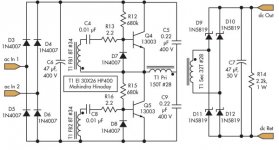
Simple amp. based on SG3525 PWM IC.
Frequency is fixed to 150kHz (fixed f is good choice) but you can modify it by changing RT/CT.
PWM is ~2-98% (which is very good).
IR2184 is HI/LO side gate driver.
Dead time provided by this IC.
Set the potentiometer on half.Turn amp ON.Set output voltage to 0V.
This amp works from first attempt 😉
On PCB i have to use external 12V PSU for IC's
Max input voltage is +-80V.
With 4k7 adjust gain.
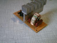
Output inductor is gapped core (can be used yelow toroids from AT/ATX PSU,they have internal gap.
In external 12V version you can regulate the output power only by voltage on fets.
12V is referenced to -V,not to GND!
On picture I used totem pole output instead of FET's and driver IC,but I tested wih IC and FET's too.
Hi acca,
Sorry for silly question,could we use n channel mosfet for both high side and low side with split supply?Thanks,this is my first class d trial.
Hi acca,
Sorry for silly question,could we use n channel mosfet for both high side and low side with split supply?Thanks,this is my first class d trial.
Yes you can,thanks to ir2184 gate driver
For a long time I searched for a cheap amplifier.
That is why I want class D.
I think no longer use the heatsink, so will be cheaper.
However, if you need to use heatsink, I do not see the advantage.
Heatsink for 2x100W TDA8920Buy TDA8920 BTH Class D Power Amplifier Board (2 x 100W / AC 12.5~20V)
I do not have a better solution. But I still think it.....
I was thinking about putting two TL494 in master-salve configuration.
And if you make a small difference in feedback voltage of these two TL(resistive divider), you will create a dead-time between those two TL(one for the low side, one for high side)
I can say what I thought,
For a 'correct' dead time, you need need a digital circuit, as they did here with gates A1,A2 :
http://geekcircuits.com/wp-content/uploads/2010/07/tl494-class-d-power-amp1.png
Because the signal is too weak, after these gates, you need a MOSFET driver (IR2010).
The price of IR2010 plus the remaining components It's almost as the price of IRS2092.(SMD version of IRS is cheaper). (Using this IRS, your risk of error is less)
I already ordered the IRS.
Still looking for very cheap variant class D amplifier (price of TL494 is less than SG3525)
Last edited:
Ir2011 has internal deadtime,and deadtime can be added with 1 resistor to sg3525,and im sure it can be added to tl494
Hy. This will be my first Class D amplifier that i will build. I have read the entire posts of this subject and i am a little bit confused and i want to know if is better to build the one from post 268 adding to schematic the capacitor from line in or the one from the first post? And irfz48 it will serve?
I will use it for listen some music at home not hi-fi.
I have 2 speakers home made(Visaton speakers) to convert them into active speakers. I want to apply 100W/8ohm for woofer and 60W/8ohm for mid and hf. Is this possible with a smps at 56Vcc made from a ATX power supply conversion?
At this momment i am using 2 motoamp from DjLeco and the sound is great but i want to try a classD to make them active and looks cheap and good quality as i´ve read about it.
Thank you and have a good weekend.
L.e: or the one from post 300?
Last edited:
Hi. Is this core (DTMSS-27/0.033/20V from tme) usable into schematic from post 268?And small test:
Klasa D sa SG3526 - YouTube
The output capacitors can be normal capacitors or it must be Low ESR?
I have seen people using sendust cores, like those you showed for class d amplifier,output caps need to be low esr
Acca,
Thank you for sharing your creative and unique designs with us🙂
I have simulated post #275 in LT Spice. It works, but
I am concerned with the VERY HIGH current through diodes D4 and D5. Is this normal? Do the diodes in your prototype get hot or fail? I simulated them as 1N4148.
Thank you for sharing your creative and unique designs with us🙂
I have simulated post #275 in LT Spice. It works, but
I am concerned with the VERY HIGH current through diodes D4 and D5. Is this normal? Do the diodes in your prototype get hot or fail? I simulated them as 1N4148.
- Status
- Not open for further replies.
- Home
- Amplifiers
- Class D
- DIY Good Class D amplifier