If I use +/-32V for FE2022, How do I change any value ?
I built the diyAudio Store DIY FE2022 and powered it with a +62V supply, which is equivalent to +/=31V. The only components that I changed were C4/C5, which I changed from 25V to 35V.
I am quite pleased with the results. FFT results here: My +62V PS DIY FE2022 FFTs

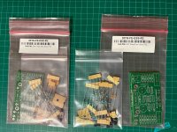
Just received the pcb's today. It came with 26 resistors. Would be grateful if someone could let me know how to pick R7 and R8. Thanks
Those are the values listed in the DIY FRONT END paper by Nelson Pass. But I also understood that the measurements of Q3 and Q4 would determine the actual values of R7 and R8. That these resistors are matched to the Jfets.
My kit from the diyAudio Store had resistors that matched the schematic values for R7 and R8. It did not have 26 resistors. Looking at the diyAudio Store page for the DIY Front End 2022 kit, only the four resistors for R7 and R8 are included. My kit also had only the four resistors.
What kit did you purchase that has 26 resistors?
What kit did you purchase that has 26 resistors?
I received my front end cards, thank you store, but it is I gather an updated version. Is there a new .pdf for the newer card to describe the differences? Looks like a varistor input in there or some thing three pronged.
Hello cjfrbw,
the three legged part should be the added trimpot for offset- adjustment. But I am not sure - did not see the new pcb.
Greets
Dirk
the three legged part should be the added trimpot for offset- adjustment. But I am not sure - did not see the new pcb.
Greets
Dirk
The V0R0 boards came with just the resistors needed to bias up the constant current Jfets
at the proper current. When it came time to assemble the kits for V0R1 I decided to not be
so lazy and included the remaining resistors plus a couple more. The resistors to bias the
constant current sources remained the same because I was still working out of the Jfet bin
with the Vp that matched. As it sits now, the only additional parts you will possibly need are
the caps and the potentiometer for offset adjustment. The pot is only needed if you are direct
coupling. You will also note that the holes for the film caps accommodate a range of lead
spacing....
Thank you Nelson!
You mentioned that adjusting the offset will increase THD, how much we are talking about? I am just trying to understand what would make me sleep better having that output cap or larger THD due to the pot 🙂
You mentioned that adjusting the offset will increase THD, how much we are talking about? I am just trying to understand what would make me sleep better having that output cap or larger THD due to the pot 🙂
Last edited:
Thank you, I got the updated information on the boards. Also, thank you to the store for providing the resistors. Now, another groovey noobie question, where do you put the output signal ground on the board? Would that be on the GF(?) under the red adjacent to the OUT?
Attachments
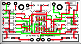
Location of Ground for both input and output signals depends on the power supply.
If the power supply is bipolar, Ground is at VG.
If the power supply is V+, omit R10 and jumper with a wire, and Ground is at V-.
If the power supply is V-, omit R9 and jumper with a wire, and Ground is at V+.
P.S. See Nelson's post #1 for his article which explains it all, and also his post #686 which I referenced in post #791 for his V0R1 board information.
Last edited:
Thank you. I thought that would be the case for single ended. I plan single ended operation rather than bipolar..
Connector GF is for external feedback if desired.Now, another groovey noobie question, where do you put the output signal ground on the board? Would that be on the GF(?) under the red adjacent to the OUT?
- Home
- Amplifiers
- Pass Labs
- DIY Front End 2022