Best performance will be at high rails. But I personally would not push this one over maybe +/- 30V. The resistors (R7, R8) in the kit are meant to be used with the particular CCS J113's that they give you, in order to set the intended current through Q3 and Q4. A matched pair of K170's will work great at Q1 and Q2, use 'em if you got 'em.
edit Well maybe better stick to +/- 25V with the Toshiba's... I'm spoiled with the cascode in my FE where I don't have to lose sleep over the excess voltage thing... Pushing the drain to source voltage on the K170 much over 40V will likely break them.... "3 legged fuses"....
edit Well maybe better stick to +/- 25V with the Toshiba's... I'm spoiled with the cascode in my FE where I don't have to lose sleep over the excess voltage thing... Pushing the drain to source voltage on the K170 much over 40V will likely break them.... "3 legged fuses"....
Last edited:
I think Zen Mod is vastly overqualified to do that ... 😆My son matches the J113's and I do the Toshiba's
Will 2SK170BL's at Q1 and Q2 also work well at 48 volts, or are these fets at a greater risk of breaking down?
Hello Leicaphile27,
the Toshiba 2SK170 start to get in 'danger' at around 34-35 V. Nelson Pass reported that they breakdown at around 40 V. I never tried 40V.
Datasheet also points to 40 V (Vgds).
I am pretty sure he will answer...
Cheers
Dirk
the Toshiba 2SK170 start to get in 'danger' at around 34-35 V. Nelson Pass reported that they breakdown at around 40 V. I never tried 40V.
Datasheet also points to 40 V (Vgds).
I am pretty sure he will answer...
Cheers
Dirk
Usually the 2sk170's are close to 1/2 the sum of rails. If you are climbing above 30 volts you start looking at cascoding.
And dissipation starts to get out of hand for these little TO-92 devices when you start cranking these rails up in a project like this. The KSA992 and J113 may be OK voltage wise but the junction temps get pushed to a level that is probably not conducive to the long term reliablity of those guys. They have those little slip-on heatsinks but I'm not sure how effective they really are.
Hello frontend2022-builders,
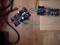
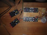
I made a new 'start-up' with this nice circuit. Made some new pcbs with more possibilities for experiments.
At Q1/Q2 I used Toshiba 2SK170 GR with an Idss of 6,81mA. Very well matched.
I exchanged the KSA992 against a ZETEX FZT951. Running at 9.8 mA. Why? Because I wanted to test it... It is a very low noise BJT.
Some adjustments to the resistors to get the DC-offset before the outputcap C3 to 1-2 mV. Behaves stable.
Very important: railvoltages have been reduced to +- 16 V DC - I didn't want to cook those precious Toshibas

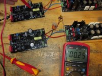
After the 47 Ohm resistors (R9 / R10) I was anywhere around +- 15.5 V DC.
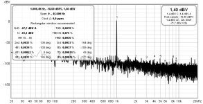
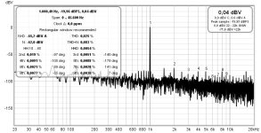
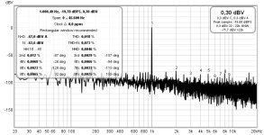
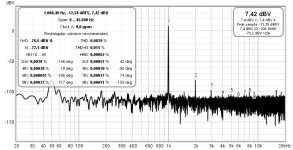
Then I made some measurements with the Focusrite Scarlet and REW.
Tried inputvoltages 100 mV / 500 mV / 1v sinus at 1 kHz. At output of the frontend 2022 - a 10kOhm resistor.
With 100 mV sin in I measured slightly above 1 V sin out.
And I've got this - in the pics...
Perhaps I can listen to this little creatures this evening?...
And they need some more adjustments...
Only some infos about my journey into this circuit.
Have a nice sunday!
Dirk 🙂
I made a new 'start-up' with this nice circuit. Made some new pcbs with more possibilities for experiments.
At Q1/Q2 I used Toshiba 2SK170 GR with an Idss of 6,81mA. Very well matched.
I exchanged the KSA992 against a ZETEX FZT951. Running at 9.8 mA. Why? Because I wanted to test it... It is a very low noise BJT.
Some adjustments to the resistors to get the DC-offset before the outputcap C3 to 1-2 mV. Behaves stable.
Very important: railvoltages have been reduced to +- 16 V DC - I didn't want to cook those precious Toshibas
After the 47 Ohm resistors (R9 / R10) I was anywhere around +- 15.5 V DC.
Then I made some measurements with the Focusrite Scarlet and REW.
Tried inputvoltages 100 mV / 500 mV / 1v sinus at 1 kHz. At output of the frontend 2022 - a 10kOhm resistor.
With 100 mV sin in I measured slightly above 1 V sin out.
And I've got this - in the pics...
Perhaps I can listen to this little creatures this evening?...
And they need some more adjustments...
Only some infos about my journey into this circuit.
Have a nice sunday!
Dirk 🙂
Attachments

Hello out there,
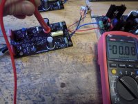
could adjust the DCoffset at output to below 1mV. They are hangin' on the better PSU.
Those 'babies' are playing music...


Cheers
Dirk
could adjust the DCoffset at output to below 1mV. They are hangin' on the better PSU.
Those 'babies' are playing music...
Cheers
Dirk
Attachments
Hello Monk55,
which voltage are you asking for? Railvoltages are at +-16 V DC. Or check post #768.
If you want to know voltages over specific resistors, feel free to ask.
Cheers
Dirk
which voltage are you asking for? Railvoltages are at +-16 V DC. Or check post #768.
If you want to know voltages over specific resistors, feel free to ask.
Cheers
Dirk
Interesting FFTs. The distortion at 0.5V in is higher than at 1V in.
Is Vsin rms or peak?
The distortion levels overall appear quite high.
Is the noise level lower with the better PSU?
Is Vsin rms or peak?
The distortion levels overall appear quite high.
Is the noise level lower with the better PSU?
Hello Ben Mah,
the generator in the Focusrite shows 100 mV RMS or 141 mV peak.
Good night!
Dirk
the generator in the Focusrite shows 100 mV RMS or 141 mV peak.
Good night!
Dirk
The latest measurement shows lower noise level, below the harmonic distortion. So the better PSU does measure better.
When I do FFT measurements, I average the results. That way the plot of the noise shows with a smaller range in levels, allowing the harmonics to be more visible if they are at approximately the same level as the noise.
I am still curious about the overall distortion levels. They appear to be quite high considering that 2SK170 were used in place of J113 at the input. The distortions are actually higher than what would be expected for J113. Could it be the Focusrite generator? You could do a loopback check of the Focusrite at its various output levels. Also the Focusrite XLR input is cleaner than the TRS input. Which input were you using?
And your 0.5V input plot showed higher distortion than the 1.0V input plot. Perhaps they were mislabeled?
Good Morning,
I have used the TRS-input. Will make a loop-check with the Focusrite.
greets
Dirk
I have used the TRS-input. Will make a loop-check with the Focusrite.
greets
Dirk
- Home
- Amplifiers
- Pass Labs
- DIY Front End 2022