Totally understood.fact - some ppl are taking one Vbe as 600mV, some as 650mV, some as 700mV
ignoring that really depends of exact part and current trough, it is basic figure used as guide; tight guide, but not exact number carved in stone
What I was trying to say is: it could be wrong to spend a lot of time to persuade zero offset. It might not be necessary.
with output cap in place, getting in ballpark is enough
say that +/-100mV is ballpark, at least looking from ZM Chicken chair
say that +/-100mV is ballpark, at least looking from ZM Chicken chair
The circuit must have the input capacitors. I also know that properly-sized coupling capacitors have so little effect on the sonics that I don’t worry about it at all.
Reducing offset to an absolute minimum is an interesting engineering exercise. (Though it will vary quite a bit with temperature.) And worth messing around with.
That said, you still will need the output cap.
Reducing offset to an absolute minimum is an interesting engineering exercise. (Though it will vary quite a bit with temperature.) And worth messing around with.
That said, you still will need the output cap.


.........
but there are numerous options for single-ended input, single-ended supplies and gain. The
power supply filter can also create a virtual ground for single-ended supply operation with
either V+ or V- referenced to a Ground.
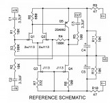
As a concept you can DC couple the whole thing with bipolar supplies and a pot to trim the offset.
Oof, it makes me nervous to imagine removing C2 in particular, when using balanced inputs such as from an XLR connector. As its name suggests, DC coupling guarantees that if there's DC (offset) on the input, there will be DC on the output. But removing C2 means the DC on the input is amplified by 10X and presented at the output. Oof. If there were a "DC servo" to remove output offset -- sure, no problem. Without a servo, you're at the mercy of whatever gear someone connects to the input. You can trim a pot to give zero offset at the output with the input shorted; but then when somebody connects a source that has DC offset, kaboom, 10X DC offset at the output. Oof.
For balanced inputs, I'd feel a LOT safer including C2 (and C1 for symmetry) rather than removing them.
Attachments
Last edited:
Probably an exercise reserved for the FAB elite… 😀As a concept you can DC couple the whole thing with bipolar supplies and a pot to trim the offset.
...
could be that anything is wrong with my measurements. I also saw the pretty high distortion.
Inputvoltage was 2 V sinus, at output 10kOhm resistor. Forgot to measure outputvoltage.
The limit range is reached with an input voltage of 2 volts and a supply voltage of -/+ 20 volts.
The displayed values of the distortion are probably correct.
Nelson didn't you mention in a vidio that a small amount of DC offset
might not be a bad thing after all.
might not be a bad thing after all.
Hello out there,
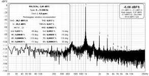
I have to apologize for my measurements (post #272). I was downloading new asio-drivers. I think I had problems there... 🤔
Today I made a new measurement on the Frontend2022: input voltage was 500mV rms (sinus / 1000Hz), 10kOhm resistor at the output, I measured something around 2 V AC / 1000Hz at the output (with a Fluke).
I didn't want to confuse anybody or wanted to query measurements of Mr. Pass! I only wanted to see what makes that circuit I am playing with...
In the pics is, what I got today:
Cheers
Dirk
Attachments
Hi Dirk,
did you measure the input and output voltage with the Fluke?
The frontend has a gain of 20dB (x10), with 500mV at the input, 5V should appear at the output.
But maybe I'm wrong.
did you measure the input and output voltage with the Fluke?
The frontend has a gain of 20dB (x10), with 500mV at the input, 5V should appear at the output.
But maybe I'm wrong.
The ratio of a couple of resistors sets the gain of an op-amp, discrete or otherwise. The .pdf in post #1, just beneath the parts list, explains which resistors you can change to adjust the gain for your own needs.@6L6, @william2001- thanks for your replies. My speakers aren't really demanding 4 ohm loads - I use a pair of Zu and a pair of Linn Ninkas.
I don’t play very loud. The F4 seems to be a great sounding amplifier but requires some gain up front. I think the gain on the new front end is up to 10db?
Some amplifiers don’t need more than a pot to control volume - maybe the F5 is in the category. Also wonder is this front end with the F5 is too much rain overall for my use.
Thanks again - bmdduck
Oof, it makes me nervous ......
For balanced inputs, I'd feel a LOT safer including C2 (and C1 for symmetry) rather than removing them.
Well, DC couple the whole thing means removing all C1, C2, C3, not ?
Just like any IC opamp. This is just a discrete opamp, as in the original article.
To enable DC couple and improve bias stability, I would :
a) Use J111s for Q3,4 and much larger resistors at R7,8. This will improve bias stability significantly by degeneration feedback.
b) Add a diode D1 and a resistor R9, where D1 should be thermally coupled to Q5 to track its Vbe drift.
(b) will actually improve intrinsic linearity and reduce distortion as a side benefit.
Trim DC offset with R8.
Again, only Spice. Not built.
Cheers,
Patrick
Attachments
Last edited:
- Home
- Amplifiers
- Pass Labs
- DIY Front End 2022