I have the CM6631 usb daughter board installed, works perfectly. I guess it is SPDIF directly to the dac. It sounds good to me, stable no dropouts driver works perfectly as regular usb2 audio and ASIO. Will USB to i2s fed directly to the dac give a big advantage and if so, why?
BR Christian
BR Christian
soundwise the difference would be small i guess. i mentioned it because i dont like the fact that the option is a daugtherboard and there is no i2s output although it would be possible. but if it works ok for you then thats the most important bit.
Hi friends,I came across one link which uses WM8742 & this chip is said to reach 99% close to performance of Sabre32 DAC.
WolfsonWM8742DAC
So anyone tried?
Is there any kit available for WM8742 chip?
WolfsonWM8742DAC
So anyone tried?
Is there any kit available for WM8742 chip?
what a ridiculous claim, subjectively its meaningless as a sweeping statement and objectively its simply not true.
ok i made a first attempt to get i2s yesterday with no success. Connections were towards diyinhk xmos board. The connections from the dac pins to xmos were the following:
pin 59 DATA1 = LRCK
pin 58 DATA2= DATA
pin 60 DATA_CLK=BCK
pin 51 gnd= gnd
Also to note that the dac by default has data3-data5 shorted. I didnt fiddle with that and left as it was.
it was a real pain to even make the connections so a bit disappointed not to get anything out of it, but happy that i didnt bricked the dac in the process 🙂
The xmos now is not recognised by the pc which is something experienced by this guy as well until he modded the xmos grounds: XMOS 384Khz Asynchronous USB to I2S | myl8test
i guess that if i disconnect it from the es9018 it will get recognised normally as before.
any help would be much appreciated, as i am just learning how these things work
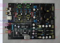
I have one of this boards in a nice case. The DAC sounds fine to me. It is especially good on poor sources, because of the great jitter-reducing properties of the SPDIF receiver. I have used it with good results with a satellite radio receiver, an Apple-TV and a (broken) SONY SCD-C555ES CD changer.
Before talking about my own system, I want to point-out how this board is reasonably well-designed – for the price point. Because the ~100USD price of the basic board in kit form (including the ESS9018 chip,) it was not possible to include amenities like I2S input and a discrete regulator for AVCC. However, this is still a subjectively good-sounding DAC.
Objectively, the SPDIF receiver of the ESS9018 DAC is excellent, with exceptional resistance to jitter. As for the use of monolithic regulators for AVCC, this board uses the ADP150 ultra-low-noise regulators from Analog Devices.
The ADP150 is a new-generation chip with a very low noise figure (something like -111dB, I estimate.) The particular regulators used are the ADP150AUJZ-3.3 3.3V regulators in 5-lead TSOT (tiny) packages - as can be seen from the “LEJ” branding on the packages. (This information is from the Analog Devices application note “ADP150 Ultralow Noise, 150 mA CMOS Linear Regulator.”)
Three AD150s are used. Two are for AVCC (right and left use separate regulators.) One is used for the XTAL (AD explicitly mentions “RF, PLL, VCO, and clock power supplies” as applications for the AD150.) Because the ADP150 can use a maximum 5.5V input voltage, LT1085-5 5V 3A pre-regulators are used. One feeds only the ADP150 for the XTAL. The other feeds two ADP150s (for AVCCL and AVCCR) and two LT1117s (for 3.3V and 1.2V digital.)
I enclose a figure with the regulators labeled (the labels are to the right of the regulators.)
Because the AD application note stresses the need for low-ESR capacitors after the ADP150, a possible area of improvement is substituting the generic 100 uF, 16V electrolytics after the ADP150s for AVCC(L&R) with low-ESR caps, for instance ELNA ROA (cerafine) 220uF 25V or 330uF 16V. I will report on the effects of these upgrades.
As for the op-amps, I will try TI OPA827s for both the single and dual positions, with decoupling capacitors soldered directly to the DIP to SOIC adapters.
Attachments
including i2s inputs doesnt cost anything at all. making proper layout, also comes cheap, if you claim to be a designer of proper layouts. multilayer would be preferred, but 2 layer could be made to work
ADP150 is not suitable for any of the analogue supplies, despite what the designer might tell you. the ADP150 is a plain vanilla, not particularly low noise LDO with typical pretty slack transient response, that costs $1 singly, buy 100 or more as he would have and its 70c each, is that what you want for the low noise stages?
ADP150 is not suitable for any of the analogue supplies, despite what the designer might tell you. the ADP150 is a plain vanilla, not particularly low noise LDO with typical pretty slack transient response, that costs $1 singly, buy 100 or more as he would have and its 70c each, is that what you want for the low noise stages?
The cost of i2s is the micro controller needed to switch the dac from spdif to i2s mode. I am using only spdif, by the way.
You cannot use $10 parts in a $100 board. Basic economics.
Analog Devices advertises the ad150 as ultra low noise, suitable for analog applications. AD also explains that larger output caps improve the transient response. So I am just reporting what AD is saying, not the designer.
Finally, this thread is for people that actually have one of these boards and want to use/improve it or are interested in getting one. They have to understand that this is the cheapest system using the ESS9018, and it does not and cannot reach its full capabilities. In particular noise figures will not be as low as advertised in the literature. For instance, I will use OPA827s instead of AD797s, despite the fact that the OPA827 has over four times the voltage noise of the AD7979. I don't care: the OPA827 sounds better to me.
I guess if the DAC is set with spdif_autodetect ON, then it would switch from i2s to spdif automatically, if a valid spdif signal is detected, overriding i2s. Would this work?
thanks for this nphil. It took me a couple of days to find the ad150 because the only marking is that bloody LEJ....
in my dac there is one ams1117 aka Linear alternative and an LT1129 (the one nearest to the clock). I think that all regulators will benefit from low esr output caps directly at the pins, they are too far as they are now. The spdif has an lmv7219 and its nicely arranged with caps close to output and input. Let us now of your progress.
As for the i2s i am still in the dark
You cannot use $10 parts in a $100 board. Basic economics.
you cannot use 70c LDO alone, for a low noise analogue supply, basic electronics ...
especially if you print the datasheet headline specs on the product page like they mean something ... low noise and suitability for this application cannot be defined by a single number, even if it was low enough. they mention nothing of such critical applications as they are used here, the spec just isnt up for it.
making an ESS for 100 bucks is a ridiculous notion to begin with. instead of fitting average components without even implementing them properly, so that people have to buy stuff twice. many things are not really needed at all, like screw terminals. it would be better to fit a few more passive components and be smart with the layout, which costs almost nothing.
with supplies like the clock supply in particular, just a couple bucks in passive components for a low pass filter after a pretty basic regulator would get much lower noise, which is much more important than low impedance here. you can try adding these on a small bit of perfboard.
no, larger low impedance caps are not always the best choice, it depends on what you are trying to do and remember that large electros are inductive and thus high impedance at higher frequencies and will impact on the response. remember that you have to increase the regulator input cap to the same value as the output cap. they wont get rid of the resonant peak in the regulator output impedance, they'll just push it around
if you do make it rather large though, add a small 1-10Ω resistor at the regulators output before the cap, this will help buffer it from the too large cap.
For instance, I will use OPA827s instead of AD797s, despite the fact that the OPA827 has over four times the voltage noise of the AD7979. I don't care: the OPA827 sounds better to me.
hes spent more attention on the opamp PSU, which have much higher PSRR than the DAC analogue stages and clock, its all backwards. I agree with your choice of the 827 here, I like it too, it has excellent AC performance, very low input bias and its a jfet input opamp, so will have better RFI immunity vs AD797, so its a decent trade-off.
I guess if the DAC is set with spdif_autodetect ON, then it would switch from i2s to spdif automatically, if a valid spdif signal is detected, overriding i2s. Would this work?
yes you can indeed have both connected, I cant remember offhand which spdif pin is able to be used without the microcontroller (in defaults), its not all of them and ideally you would not want the i2s signal playing at the same time. but hes made any attempt at i2s connection a hack job. spdf_autodetect is on by default, but so is 'lowest' dpll bandwidth, which will make for being picky of i2s source and lock may be a bit unstable
Last edited:
I guess if the DAC is set with spdif_autodetect ON, then it would switch from i2s to spdif automatically, if a valid spdif signal is detected, overriding i2s. Would this work?
Thanks for sharing. Switching spdif <-> I2S with autodetect might not be straightforward. At the minimum you need to sort out the connectors and have a multipole relay to move the signals in-out.
I think having just spdif input is a wise decision given the price/market. It is definitely more "robust" than the I2S input.
ok i made a first attempt to get i2s yesterday with no success. Connections were towards diyinhk xmos board. The connections from the dac pins to xmos were the following:
pin 59 DATA1 = LRCK
pin 58 DATA2= DATA
pin 60 DATA_CLK=BCK
pin 51 gnd= gnd
Also to note that the dac by default has data3-data5 shorted. I didnt fiddle with that and left as it was.
it was a real pain to even make the connections so a bit disappointed not to get anything out of it, but happy that i didnt bricked the dac in the process 🙂
The xmos now is not recognised by the pc which is something experienced by this guy as well until he modded the xmos grounds: XMOS 384Khz Asynchronous USB to I2S | myl8test
i guess that if i disconnect it from the es9018 it will get recognised normally as before.
any help would be much appreciated, as i am just learning how these things work
Those are the right connections. data3-data5 shorted is also correct. If the DAC is configure for spdif which uses data1, perhaps all other pins are grounded?
@qusp
You claim any low noise regulator IC do not have sufficient noise performance for ES9018's AVCC, doesnt you?
I agree to such a opinion, because ES9018 have no PSRR and ADP150 or even TPS7A4700 have much lesser noise performance compared to AD797, recommended in ESS's paper.
I assume,
At bipolar zero ,the noise from AVCC will be almost canceled out by differential to single synthesis, depend on CMRR (resister tolerance will limit it).
So superior SNR at BPZ will not be contaminated.
But at other than BPZ, the noise will reside in analog output amount of |N-32|/32*2*Vn at N level output of 64 pk-pk level even in infinite CMRR.
Therefore the performance will degrade proportional to RMS swing level.
e.g. at full scale sine wave have the level of 32/sqrt2 = 22.8 in pk-pk 64 level,
then (32-22.8)/32*2*Vn=0.575*Vn will reside in analog output.
Consequently, AVCC regulator have an impact on SN at FSR about quater of an opamp in analog stage.
Last edited:
In the ESS application note, a simple circuit is shown that uses an opamp to clean up the AVCC supply (Fig4.) The way the circuit works it that noise on DVCC is filtered by R4 and C1, while noise on the 12V supply is reduced by the PSRR of the opamp.
It should be easy to implement such a circuit on a perfboard, using an AD797. Using this circuit would leverage the decent 15V supply to produce a clean AVCC. Main problem in actual use is grounding.
This would be a more worthwhile improvement to this system than trying to implement I2S (I think.) It is also in the spirit of DIY audio, no?
Attachments

So what is holding this dac back the most and what is worth upgrading? I have two candidates right now:
1:
I think that we can assume that the AVCC design is holding this dac back. So, how hard would it be to upgrade the AVCC? Would it be worth the cost? What is the best cost efficient solution?
2:
The caps (and opamps in my case)of the output stage. I only use the unbalanced output so the current design seem unnecessarily complicated for that use. Would it be better to connect the balanced output as a unbalanced output and remove the last opamp?
@ervstil
The last opamp does balanced to unbalanced conversion, but it also implements a low-pass filter (LPF.) The LPF is necessary to remove noise above the audio band. You would need some sort of passive LPF network, if you skip the last opamp.
Also, if you use the balanced output as unbalanced, you will need output caps to block DC. In my board, I measured a DC offset of 2mV in one channel, .8mV in the other, after the last opamp. This is acceptable. Without the last opamp, the offsets are 100mV or so.
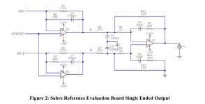
This is a schematic of the output stage (Fig2) for one channel.
U1 and U2 do I/V conversion. DAC and DACB are the DAC current outputs (DACB is the “negative” of DAC.) Note that R1 and R4 are actually 680Ohm, because four output lines are paralleled into U1 and U2 (actually a dual, I am using an OPA2604 right now.)
U3 is a single opamp and does balanced-to unbalanced conversion and also implements the LPF. I am currently using an OPA627. R8 and R9 are 22Ohm, R11 and R12 are 150Ohm (in my board,) but otherwise this is what is actually implemented.
I don't see any particular reason to skip U3, unless you are planning to use a more sophisticated way to go from balanced to unbalanced output. Simply using one side of the unbalanced output would let through the common-mode noise.
Incidentally, I am using my own OPA2604s and OPA 627s, but I don't believe that the ones that came with the board are fakes. The OPA627 is an old chip and old stock or even used – but authentic - OPA627s are available for about $3 on eBay. The OPA2604s cost even less. The OPA827 (my favorite) is a newer chip and I don't think is available for less than $10 each.
The last opamp does balanced to unbalanced conversion, but it also implements a low-pass filter (LPF.) The LPF is necessary to remove noise above the audio band. You would need some sort of passive LPF network, if you skip the last opamp.
Also, if you use the balanced output as unbalanced, you will need output caps to block DC. In my board, I measured a DC offset of 2mV in one channel, .8mV in the other, after the last opamp. This is acceptable. Without the last opamp, the offsets are 100mV or so.
This is a schematic of the output stage (Fig2) for one channel.
U1 and U2 do I/V conversion. DAC and DACB are the DAC current outputs (DACB is the “negative” of DAC.) Note that R1 and R4 are actually 680Ohm, because four output lines are paralleled into U1 and U2 (actually a dual, I am using an OPA2604 right now.)
U3 is a single opamp and does balanced-to unbalanced conversion and also implements the LPF. I am currently using an OPA627. R8 and R9 are 22Ohm, R11 and R12 are 150Ohm (in my board,) but otherwise this is what is actually implemented.
I don't see any particular reason to skip U3, unless you are planning to use a more sophisticated way to go from balanced to unbalanced output. Simply using one side of the unbalanced output would let through the common-mode noise.
Incidentally, I am using my own OPA2604s and OPA 627s, but I don't believe that the ones that came with the board are fakes. The OPA627 is an old chip and old stock or even used – but authentic - OPA627s are available for about $3 on eBay. The OPA2604s cost even less. The OPA827 (my favorite) is a newer chip and I don't think is available for less than $10 each.
Attachments
@nphil
looks like we posted simultaneously regarding the AVCC. I think it would be an interesting and worthwhile project. I have also been looking at the whitepaper, but there is some things i do not understand in that schematics. If i understand the schematics it filters the DVCC and uses it as a reference for the AVCC. Would that not require a descent DVCC? Do we have that on this board? What are the grounding issue you mentioned?
Regarding the output stage, you are of course correct. I have not taken the time think it through.
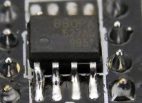
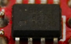
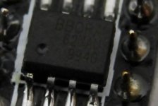
Do you really think that the OPA627 could be real for that prize? I have noticed that what is supposed to be a date and plant code does not remotely look like the date codes on the verified genuine ones. It is also identical between all opams including the ones received from another ebay seller. I have taken some pictures of the assumed fake opamps i have. The first one is what came with the dac. The second one is what came with my 'Lovely Cube'. The third is what came with another project. They are all post order from China. If they are genuine, you are correct about the age, they are from 1999 and 2001. Do the look like a real opa627? I have nothing to compare with. Is the a way to measure and verify them? A realize that the best way is to listen, but once again i have nothing to compare with.
looks like we posted simultaneously regarding the AVCC. I think it would be an interesting and worthwhile project. I have also been looking at the whitepaper, but there is some things i do not understand in that schematics. If i understand the schematics it filters the DVCC and uses it as a reference for the AVCC. Would that not require a descent DVCC? Do we have that on this board? What are the grounding issue you mentioned?
Regarding the output stage, you are of course correct. I have not taken the time think it through.
Do you really think that the OPA627 could be real for that prize? I have noticed that what is supposed to be a date and plant code does not remotely look like the date codes on the verified genuine ones. It is also identical between all opams including the ones received from another ebay seller. I have taken some pictures of the assumed fake opamps i have. The first one is what came with the dac. The second one is what came with my 'Lovely Cube'. The third is what came with another project. They are all post order from China. If they are genuine, you are correct about the age, they are from 1999 and 2001. Do the look like a real opa627? I have nothing to compare with. Is the a way to measure and verify them? A realize that the best way is to listen, but once again i have nothing to compare with.
Attachments
@ervstil
Well, they look authentic to me. Basically, if they are fake why did they use such ancient dates on them? I think they are probably real old stock.
On Digikey, a single 627AU (SOIC) costs $25.7 or so. An OPA827 costs $10.13. From my supplier (hifiic) an OPA627 costs about $4, mounted on a SOIC to DIP adapter. An OPA827 costs about $10, mounted on an adapter. This is a reliable supplier: the big difference in price is due to the fact that the 627s are ancient.
TI bought BB in 2000. They are trying to obsolete the 627, hence the high price. The 827 is their preferred replacement. They fired all the designers of the 627 and anybody who still remembers the secrets of how to make them. I think that today they are only made in a plant in Thailand. However, so many 627s were made in so many different countries that lots of old ones are available at low prices. And even at $3 each is still profitable for people in China to recover them from old boards.
- Home
- Source & Line
- Digital Line Level
- DIY ES9018 Hi-end USB DAC