Hi locky,
Based on post #349 and #351, I made the attached table for my personal reference.
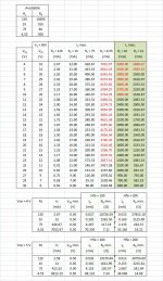
Now, the 'standard' transistor Hfe curves in almost all datasheets are tested agains either Vce = 4 volt, or Vce = 5 volt, and as such I compare new an old transistors (for vintage audio repair) at Vce = 5 volt. But if I want more than 413 mA at Vce = 5 volt, then the only option is to select Rc at 4.55 ohm.
Now, looking at the attached table, I have the question why you made the lowest Rc at 4.55 ohm? As the red numbers show, the normal power supply for this unit would not be able to operate above 2500 mA. I added values for 10 and 12 Ohm for comparison. I would think that those values would have matched reality a bit better. And heat dissipation of Rc will be lower accordingly, and accuracy might improve as well.
Of course, the current can be limited in the set-up; so no issue.
PS: this is not a complaint; I'm happy with your tracer, I just wonder why you installed 4.55 ohm resistor.
Ozzy
Based on post #349 and #351, I made the attached table for my personal reference.
Now, the 'standard' transistor Hfe curves in almost all datasheets are tested agains either Vce = 4 volt, or Vce = 5 volt, and as such I compare new an old transistors (for vintage audio repair) at Vce = 5 volt. But if I want more than 413 mA at Vce = 5 volt, then the only option is to select Rc at 4.55 ohm.
Now, looking at the attached table, I have the question why you made the lowest Rc at 4.55 ohm? As the red numbers show, the normal power supply for this unit would not be able to operate above 2500 mA. I added values for 10 and 12 Ohm for comparison. I would think that those values would have matched reality a bit better. And heat dissipation of Rc will be lower accordingly, and accuracy might improve as well.
Of course, the current can be limited in the set-up; so no issue.
PS: this is not a complaint; I'm happy with your tracer, I just wonder why you installed 4.55 ohm resistor.
Ozzy
Attachments
Mainly for the following reasons:Hi locky,
Now, looking at the attached table, I have the question why you made the lowest Rc at 4.55 ohm?
Ozzy
1.The the maximum output voltage is only 36V(It limited by the op amp).
2.My initial design, the maximum measuring current of 5A, and each PCB actually can work in 5A current.
3.Most of the transistor Hfe-Ic curve is under Vce = 5 or 10V.So the maximum voltage on RC is 25V, So RC = 5 ohms is best.The my early have used 6.8 ohm / 4.7 ohm.I'm here with 4.55 ohm reasons is more I have 9.1 ohm resistor.
The PCB compent can work in 5A,But why I set them only work under 2.5A?
Because the HP switch power supply only can output 2.5A, If exceeded, the power will be shut down. you need to restart the power it.
So I produced, select R48 and R50, so that the protection circuit of each PCB around at 2.5A effect.
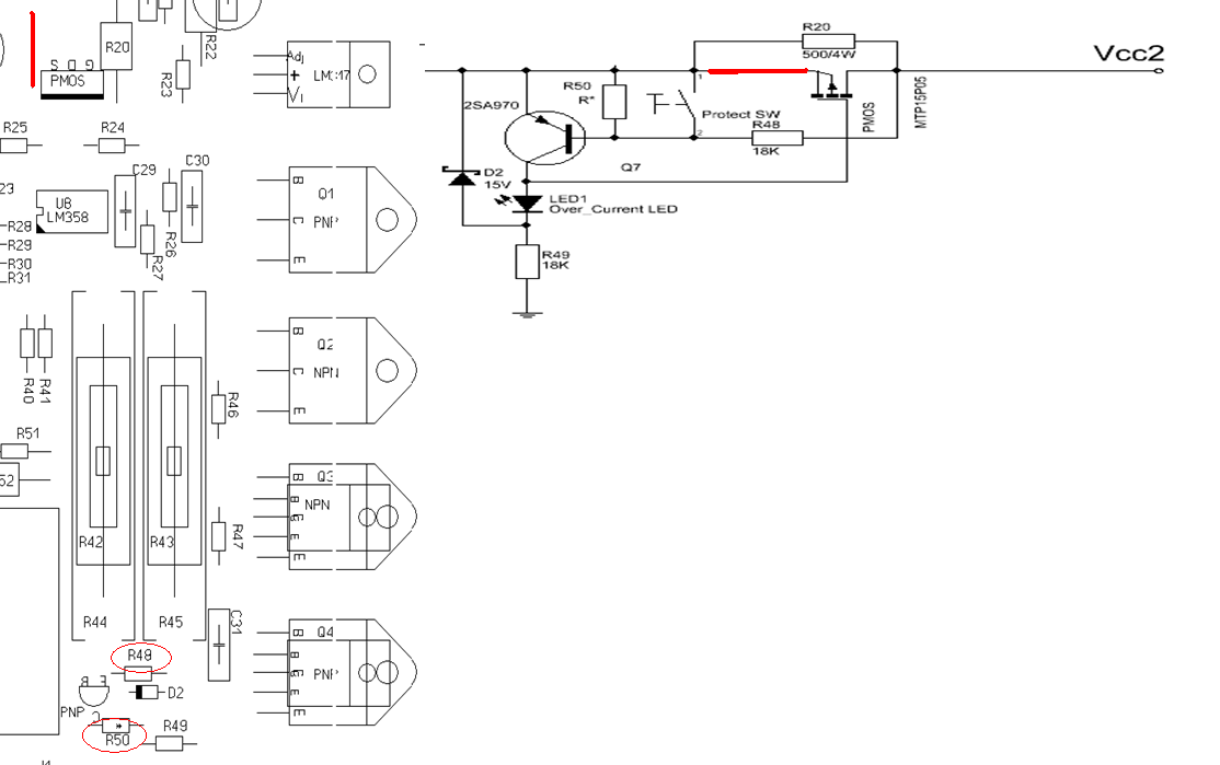
If you have a enhanced power supply, you can change the R48 & R50 to increase the protect current.
Hi Locky,
Well that explains it; thanks. And now I know why you did put two 9.1 ohm power resistors in parallel.
If there would be a future new version of this tracer, perhaps you can add some Rb and Rc values?
Well that explains it; thanks. And now I know why you did put two 9.1 ohm power resistors in parallel.
If there would be a future new version of this tracer, perhaps you can add some Rb and Rc values?
Hi,
I suspect there may be an issue with the equipment, so i`m asking for your advice.
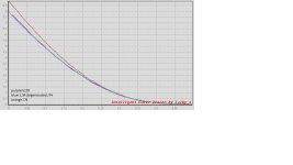
The part being tested is ZVN3310A mosfet.
You see, the dotted line i marked is like a logical continuation of the curve, The discontinuation looks like an error of some kind..
I may be overlooking something.. ??
Thank you all.
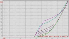
Someone also have the problem .He measure the 2SK2013,measure condition is Vb: 0.5V – 3V, RB: 500, RC:4.55, Imax: 500m A, Constant Vce=20V
He get this picture.
I think it may be oscillation. But I havn't those transistor, and I don't know how to solve it.
After a few day , He send me get the email about the solution.
"The equivalent of measuring power mosfet need line connection socket with the heat sink DUT cable is too long, some components will occur oscillation.
So series a 100 ohm resistor in gates then solve the problem."
Attachments
SJ74 & SK170 matching
Hi,
I hate to bring this up again, but could someone advise how to do #5?
I manually inserted resistors between jFet source pin and tracer, and while this works, it is a bit time consuming.
True.
But even easier:
1) Trace all the FETS without any kind of degeneration.
2) From the traces sort and record Id @ 0V and 0.1V
3) Copy to excel (and fix all the stupid decimal and errors😡)
4) Calculate Yfs = (Id@0V-Id@0.1V)/0.1V
5) Recalculate Idss and Yfs for the J74 using selected Rdeg values (I use 4R3, 4R7, 5R1, 5R6, 6R2, 6R8 and 7R5).
Congratulations! - you now have 7 times as many J74 devices to choose from😀
6) Match you K170 and degenerated J74 devices for both Idss and Yfs.
7) Remeasure (or trace) the pairs/sets you have identified, but now with degeneration and be ready for a pleasant surprise😎
Hi,
I hate to bring this up again, but could someone advise how to do #5?
I manually inserted resistors between jFet source pin and tracer, and while this works, it is a bit time consuming.
Attachments
Trust Mr. Ohm & Mr. Pass😎
In F5 manual you can read:
"The transconductance for a JFET is the ratio of current change against input voltage change. The gain of this part is typically 0.02 Siemens, or .02 amps per control volt, and if you invert that you get 50 ohms (R = V/I). So it looks as if there is 50 ohms inside the part (although there isn’t), and to that we add the 10 ohms of real resistor to get 60 ohms."
The FET and the source resistor thus behave as series resistors and according to Ohm's law we get:
R (total) = R (fet) + R (deg) or
1/Yfs(deg) = 1/Yfs + R (deg) or
Yfs(deg) = 1/(1/Yfs + Rdeg)
Check with Nelson's numbers:
1/60R = 1/(1/0.02S + 10R)
How does Id change?🙄
Trust Mr. Ohm & Mr. Pass😎
In F5 manual you can read:
"The transconductance for a JFET is the ratio of current change against input voltage change. The gain of this part is typically 0.02 Siemens, or .02 amps per control volt, and if you invert that you get 50 ohms (R = V/I). So it looks as if there is 50 ohms inside the part (although there isn’t), and to that we add the 10 ohms of real resistor to get 60 ohms."
The FET and the source resistor thus behave as series resistors and according to Ohm's law we get:
R (total) = R (fet) + R (deg) or
1/Yfs(deg) = 1/Yfs + R (deg) or
Yfs(deg) = 1/(1/Yfs + Rdeg)
Check with Nelson's numbers:
1/60R = 1/(1/0.02S + 10R)
How does Id change?🙄
Thanks Nic.
According to Ohm's Law, as R increases then I decreases (assuming V doesn't change).
I my example the theoretical didn't match the actual, although this could be within the margin of error I suppose.
In my hands the in silico matching is very reliable.Thanks Nic.
According to Ohm's Law, as R increases then I decreases (assuming V doesn't change).
I my example the theoretical didn't match the actual, although this could be within the margin of error I suppose.
Try this equation:
Id (deg) = Id/(1 + Rdeg*Yfs)😉
Someone also have the problem .He measure the 2SK2013,measure condition is Vb: 0.5V – 3V, RB: 500, RC:4.55, Imax: 500m A, Constant Vce=20V
He get this picture.
I think it may be oscillation. But I havn't those transistor, and I don't know how to solve it.
After a few day , He send me get the email about the solution.
"The equivalent of measuring power mosfet need line connection socket with the heat sink DUT cable is too long, some components will occur oscillation.
So series a 100 ohm resistor in gates then solve the problem."
MOSFET's have always been hard to test in fixtures. They are also hard to use for the same reason. They are prone to source follower oscillation with the high impedance and high gain ant high frequencies. Ferrite beads are usually used to control that in the test fixtures (Tek, HP etc.). They also don't mess up the calibrations. Use them on the gate and possibly on the source. Bigger ones don't hurt things. adding turns could cause problems.
In my hands the in silico matching is very reliable.
Try this equation:
Id (deg) = Id/(1 + Rdeg*Yfs)😉
Well, I'm not saying it isn't reliable.
SJ74 Yfs = 0.034950732
theoretical Yfs(3.3deg) = 0.031336465
theoretical Id (3.3deg) = 7.584071234
Measured Yfs(3.3deg) = 0.030164501
Measured Id (3.3deg) = 7.6318326
As you can see, quite close. If you rounded Id to tenths they would both be 7.6mA.
However, the measured Yfs is predicted by 4.5ohm degen vs the 3.3ohm actual.
Hi all,
I was looking into buying one of this for my projects.
Where is a good place to buy it? ebay?
Is the software in chinese or there is an eglish version as well? Is this device proven to be reliable?
Thanks.
I was looking into buying one of this for my projects.
Where is a good place to buy it? ebay?
Is the software in chinese or there is an eglish version as well? Is this device proven to be reliable?
Thanks.
Bot mine off eBay - works like a charm so far 😉
Manual is rudimentary but learning to use it is easy.
Really cool tool!
If you need help many on these lists can chime in. I use it for mosfets and jfets so can't say much about BJTs....
Manual is rudimentary but learning to use it is easy.
Really cool tool!
If you need help many on these lists can chime in. I use it for mosfets and jfets so can't say much about BJTs....
Take the cased version from e-bay. The tracer is very reliable and accurate. Simple mods can improve it current capability.
Last but not least: the maker is a very smart and helpful guy (even if his english could improve🙂)
Last but not least: the maker is a very smart and helpful guy (even if his english could improve🙂)
Hi Locky,
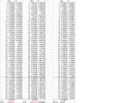
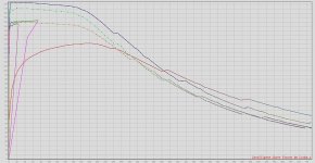
I was a very happy user, but the tracer has a serious problem after testing a faulty transistor which has E-C shorted. Sometimes it works normal for 5 tests, but then all next test : one or more relays are clicking very fast open-close-open-close... and the Hfe curve goes to 2000 or 10000 and Ib to 10000 mA or more.
In attached pictures, measurements are being stopped (purple lines), or very strange results.
Relay J1 and J2 are getting warm/hot after 30 minutes
What can be wrong ?
edit, attached curves are 2SC2235 transistor tests (Imax = 750 mA, Vbe=2V, Rb=6K, Rc=4.55, 10x AD sample)
unit #109
Attachments

Last edited:
- Status
- Not open for further replies.
- Home
- Amplifiers
- Solid State
- DIY Curve Tracer for PC