Every measurements of the board are OK and the first transistor checks as well 🙂
I will mount it with isolated holders in the case now.
Thank you all for the assistance.
Andreas
I will mount it with isolated holders in the case now.
Thank you all for the assistance.
Andreas
Hi all,
One question about PNP/NPN HFE graphs...
I must be missing something, But the NPN curve works backwards for some reason..
What is the referance for the HFE ?? it is declining😕
You need to checked once 'Calibration before measure' checkbox
You need to checked once 'Calibration before measure' checkbox
Board received!
Would this simple PSU with a lm317 + TIP 2955 be ok?
Thanks alot!
Attachments
Board received!
Would this simple PSU with a lm317 + TIP 2955 be ok?
Thanks alot!
Yes,you can use any regulator PSU.
Nmos and Pmos don't agree
Hi Locky_Z,
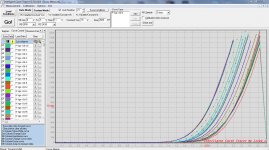
I have a problem reading the transfer curve in Pmos ( 2SJ201 ).
In similar conditions i get the complementary Nmos ( 2SK1530 ) perfect but cannot get the Pmos.
Any idea why ?
The images of both are included, with settings for ver 3.5 of software.
In the 2SK1530 plot you can see the 2SJ201 plot up to where it stops at 1.6V Vgs
Edit: the transistors are genuine !
Hi Locky_Z,
I have a problem reading the transfer curve in Pmos ( 2SJ201 ).
In similar conditions i get the complementary Nmos ( 2SK1530 ) perfect but cannot get the Pmos.
Any idea why ?
The images of both are included, with settings for ver 3.5 of software.
In the 2SK1530 plot you can see the 2SJ201 plot up to where it stops at 1.6V Vgs
Edit: the transistors are genuine !
Attachments
Last edited:
Hi Locky_z,
Here is the cuv file with a 2SJ201 and a 2SK1530, i tested a few dozen of each and they all show same disparity.
I used lots from diferent sources, Zhou-fang, Audiophonics and from other forum members including a mached NNNNPPPP set for my forthcoming F5X which i know is very well matched.
Really would like to get the most out of your great board.
Regards,
Carlos
Attachments
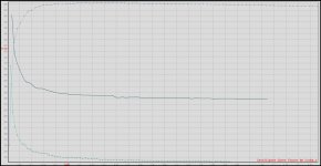
Your power supply capacity is insufficient, or something wrong with E-channel amplifier source current.
From the ‘P 2SJ201 Vgs->Id-1’ data, you look at 'Ve' column, the 'Ve' is E channel amp output voltage.
At begining, 'Ve' is 28.3V, and when current Id increases, the 'Ve' decrease.
When Ve change more than 2V,The system considers Ve not stable, so it interrupted measurement.
Because measure P type,the E channel will setup to output high voltage and source current.
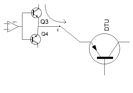
If power supply capacity is insufficient or the Q3(NPN) of E channel amp have wrong, the E channel output voltage can not keep stable.
please check the Q3(NPN) on the board.
From the ‘P 2SJ201 Vgs->Id-1’ data, you look at 'Ve' column, the 'Ve' is E channel amp output voltage.
At begining, 'Ve' is 28.3V, and when current Id increases, the 'Ve' decrease.
When Ve change more than 2V,The system considers Ve not stable, so it interrupted measurement.
Because measure P type,the E channel will setup to output high voltage and source current.
If power supply capacity is insufficient or the Q3(NPN) of E channel amp have wrong, the E channel output voltage can not keep stable.
please check the Q3(NPN) on the board.
Attachments
Thanks Locky_z,
I tried my lab supply ( 30V 6A ) instead of the HP (30v 2500mA ) one and result is the same so it's not lack of PSU current capacity,
will check Q3, right now it has the Tip132 you fitted.
I tried my lab supply ( 30V 6A ) instead of the HP (30v 2500mA ) one and result is the same so it's not lack of PSU current capacity,
will check Q3, right now it has the Tip132 you fitted.
Last edited:
Solved,
Q3 you had fitted was defective ( Tip132 ) i replaced with TIP142 and replaced Q4 for good measure with TIP 147
My only problem now is that i need a PSU that lets me measure up to 2500mA , this one will only let me go up to 2000mA without cutting off.
Even so you can see 2 traces that exceeded current capacity and droped Id to 0 !
Thanks for the tip.
Here is a picture and cuv file of measurements now. ( 2SJ201 and 2SK1530 ).
Attachments
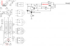
The protect circuit as below

when protect active,the C/E channel amp power supply will lost, then system will stop measure.
The R48, R50 and the Rds of PMOS and the 'red line' and the zener D2((the zener on pcb may be 6~9V) control the current protect.
If you want more current, you can do:
1. Use less Rds of PMOS
2. Increase the R48
3. Decrease the R50
4. Use high voltage zener diode replace D2.but no more than 20V.
5. Install the 'Protect SW' button(near the 'Over-current' Indicator LED),If you want more current,hold down the 'Protect SW' button, then the protect will fail.
If you want less current,you can do:
1.use more Rds of PMOS
2.decrease the R48
3.Increase the R50
4.cut off the red-line and replace with a resistor.
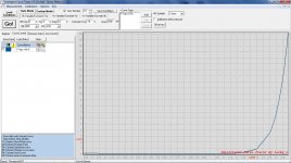
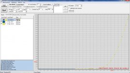
Unable to load P Conditions
This happened just now for PNP conditions, as i was running tests the Go button remains gray and unoperational.
The NPN conditions are loading properly and seems to function too.
Please see picture..
What do you think can be the cause of this??
Thanks...
This happened just now for PNP conditions, as i was running tests the Go button remains gray and unoperational.
The NPN conditions are loading properly and seems to function too.
Please see picture..
What do you think can be the cause of this??
Thanks...
Attachments
Last edited:
The device is online?This happened just now for PNP conditions, as i was running tests the Go button remains gray and unoperational.
The NPN conditions are loading properly and seems to function too.
Please see picture..
What do you think can be the cause of this??
Thanks...
The program title will be pointed out that the device is online.
If not online then goto Options->Config, click 'Auto detect and get parameter' button.
If device online and the 'Curve type' had defined,the the 'Go' button will enable.
How your error window appear?
Yes the device is online..
I suspected a program file may have corrupted so a ran a backup that i kept on a portable disk and this copy runs fine.
I tried to copy the good backup to the "Program Files" folder over the problematic copy but it still showing that issue.
Please note that this malfunction is showing only when i try to load conditions for P Hfe-Ic=% and nothing else.
But when i run the backup everything run good..
I will investigate further, but wonder what memory store other then .ini file is kpet for preferences ??...
May be something wrong in the 'ads7871_vs3.pre' file
The file 'ads7871_v3s.pre' is store the pre-define measure conditions.
Try to overwrite the ads7871_v3s.pre file with your backup.
The file 'ads7871_v3s.pre' is store the pre-define measure conditions.
Try to overwrite the ads7871_v3s.pre file with your backup.
Yes.. I tried overwriting the whole program folder and it`s still the same.
The issue is only with P hfe-Ic-% and nothing else, Should I erase that parameter and rebild it again?? Where and how do i delete it ??
Does it make any sense to approch the problem this way??
Many thanks..
The issue is only with P hfe-Ic-% and nothing else, Should I erase that parameter and rebild it again?? Where and how do i delete it ??
Does it make any sense to approch the problem this way??
Many thanks..
- Status
- Not open for further replies.
- Home
- Amplifiers
- Solid State
- DIY Curve Tracer for PC