
No, these are really just cosmetic changes. They were also made to provide the builder with more options and component choices. All modifications can be achieved with the existing boards except for the ability to use the smd melf resistors which was added just to provide more options.Should those of us who have boards from the first GB take any of these changes into account?
The only changes that I would make are the modifications to the capacitance multipler and R130, R131 which has already been discussed and the information provided
Last edited:
Hi Stuart,Hi Guy’s
As we are just about finished checking the PCB’s for the 2nd Group Buy.
I thought that I would just give you all a heads up on the minor changes / improvements we
have made to the IPS and EF3-X boards. The BOM & build guide have been updated to reflect these changes
and the Dropbox folder will be updated before your boards arrive.
IPS Boards
• Revision From 3.7 to 3.8
• Silkscreen clarity improved
Changes
• C9 now supports 12.5mm Diameter
• R121 split into R121A & R121B
Additions:
• D13, D14
• MELF SMD Pad added to R3, R4 & R7, R8
Removed:
• C11
EF3-X Boards
• Revision From 3.9 to 4.0
• Silkscreen clarity improved
Changes
• Updated the NFB Path
Additions:
• D111, D112
• D113, D114
• D115, 116
• 10mm Pitch added to C112
Removed:
• D105B, D106B on EF3-4
• D101, D102
• R130, R131
Should owners of the PCBs from the first GB, who had not built populated them yet, try to incorporate these changes, or should we be contented and happily building them as per original?
The new additions just provide more component choices for the builder and get rid of some unnecessary and unused components.Hi Stuart,
Should owners of the PCBs from the first GB, who had not built populated them yet, try to incorporate these changes, or should we be contented and happily building them as per original?
If you use the components from the latest bom and follow the latests schematic you will have no problems and your build will not suffer any degrade in performance.
The precision of R5, R26 is not particularly important.
I just joined the Wolverine club and after reading big parts of the discussion thread and the build thread i want to thank everyone who contributed to this project. I am really looking forward to build my first Class A/B amp.
While waiting for my Mouser order to arrive I was thinking about the PSU. Did i get it right that a pair of bridge rectifiers and a filter capacitance of 2x 10.000 uF is sufficient as raw PSU?
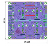
I searched for PCBs to mount the caps, but then i found a PCB design by diyaudio member @prasi . I intend to mount the SIP bridge rectifiers to the base plate underneath the board, that would free a lot of space in the small 4U 300 enclosure - plus it will reduce the amount of wiring to be made. I want to go dual mono with two transformers, so i need double the space for my PSU. The board also offers mounting pads for snubber parts for the transformer secondaries.
The board design is intended to be used as a CRC PSU, but i am planning to stuff the resistor positions with 1mm wire, so the PSU shall become a "C" instead of "CRC" design. Will this work? Please see the picture attached, wire bridges marked on the upper side of the PSU PCB.
Link to the CRC PSU thread
edit: added link to forum thread about this psu
While waiting for my Mouser order to arrive I was thinking about the PSU. Did i get it right that a pair of bridge rectifiers and a filter capacitance of 2x 10.000 uF is sufficient as raw PSU?
I searched for PCBs to mount the caps, but then i found a PCB design by diyaudio member @prasi . I intend to mount the SIP bridge rectifiers to the base plate underneath the board, that would free a lot of space in the small 4U 300 enclosure - plus it will reduce the amount of wiring to be made. I want to go dual mono with two transformers, so i need double the space for my PSU. The board also offers mounting pads for snubber parts for the transformer secondaries.
The board design is intended to be used as a CRC PSU, but i am planning to stuff the resistor positions with 1mm wire, so the PSU shall become a "C" instead of "CRC" design. Will this work? Please see the picture attached, wire bridges marked on the upper side of the PSU PCB.
Link to the CRC PSU thread
edit: added link to forum thread about this psu
Attachments
It's personal preference. I bought 4 Kemet 36.000 uF caps with screw terminals, 2 Onsemi bridge rectifiers, 1 Amplimo 1 kVA toroid and some foil caps, this for a stereo supply.
While looking throug specs of various caps, I found large differences in ESR and life expectance, this brought me to my choice.
While looking throug specs of various caps, I found large differences in ESR and life expectance, this brought me to my choice.
Because the low-pass filter propertys; Resistance, Phase-shift and Delay.
Hi Scott, This has been discussed in detail in the development thread. Please search that to find your answer. Basically it's not ideal to have your rail voltage changing as the load increases.AddiDub:
I'm curious: why not configure Prasi's power supply as a CRC instead?
Regards,
Scott
Hi Guy's,
I've started to send out payment requests for the 2nd group buy. This will take a few days to complete. Once I receive your payment I'll send you the Dropbox Link so you can access all the documentation for the Wolverine project. Please allow a few days for this to happen as its not the only thing that I have going on.
I will let everyone know when I have sent out all the payment requests.
I would be interested to know if the cap multiplier is necessary. A constant current source is used in the path.
Hi Guy's, just letting you all know that I have sent out all the payment requests. Please check your PayPal account if you haven't received it.
If you still haven't received it please send me a pm.
If you still haven't received it please send me a pm.
This amp has many design features to achieve its very low noise and distortion and the multiplier plays a big role in this.I would be interested to know if the cap multiplier is necessary. A constant current source is used in the path.
👍 @Johno
Hi guys,
I have decided too to join this great project in the 2nd GB so let me join this interesting debate.
Why would someone start a very high-quality project and then destroy it for the sake of saving a few pennies on an essential element? Based on my limited experiences, I can conclude that the use of a capacitance multiplier always improves operation of the amplifier. My all measurements support this conclusion. This is not my opinion, I am talking in terms of measurable facts.
An amplifier, in simplistic terms, basically modulates the available power so why deprive it of the chance for great performance just for slightly lower overall cost. There are some excellent capacitance multiplier PCBs designed by Prasi and they cost just pennies at PCBWay.
Hi Scott, Is there any news from your parents regarding there wolverine gift?Folks:
My integrated amplifier project is finished. It consists of a Wolverine amp (EF3-3 pcbs) and a set of RJM Audio buffer boards built in a HiFi2000 3U Dissipante chassis. The Wolverines are powered by a Jeff Young-designed "Decoupled Stereo" power supply (stereo for the first stage and then dual mono for the second). The buffers, source relays and front panel LEDs are powered by a small bipolar power supply hidden beneath the bigger supply. I modified the H9KPXG soft start board to work with a bicolor power switch and I mounted LEDs behind the attenuator and source select knobs to provide a nice knob backlight ring effect (something I've been doing for about 15 years now). This project is a gift for my parents, who listen to music all day long, and will replace a Gainclone I built for them in 2005. This will be a huge step up for them.
It takes a village to build an amp. Okay, that's not exactly true: it takes a village to help me build an amp. Although I've been building audio components for a while, my engineering knowledge is extremely limited. As a result, my projects invariably require expert support. This project was no exception, and I am enormously grateful to the Wolverine design team (especially stuartmp and jjs) for developing their amplifier, providing the Build Guide and supporting documents and then promptly and very helpfully responding to my inane questions. Honestly, this dope couldn't have done it without their help. That said, this project was incredibly fun and there wasn't a moment when I thought it couldn't be completed -- there are a lot of steps, but if you take 'em one at a time you eventually get to a successful end. And if I can do it, anyone can.
So how does it sound? After finalizing the adjustments to the amplifier (DC offset on each channel is in the 0.1 to 0.3 mV range), it was burned in for 3 days using my modified FryBaby3 burn-in device and then installed in my main system for listening tests. The speakers are Mk.6 Elsinores which have been tricked out in several ways; they're very revealing and, with good amplification, throw a broad, deep and high soundstage with exceptional resolution and neutrality. The Wolverine amp sounds fantastic: neutral, well-balanced and a very good soundstage. There is an engaging clarity with this amplifier -- eyes closed, the presentation sounds real. I could listen to this thing for hours. Unfortunately, the only way that's going to happen is if I visit Mom and Dad (I'm kidding, they're lovely people).
Kudos to the Wolverine design team!
Regards,
Scott
Hi Guys,
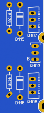
I thought you all might like a visual reference for the orientation of D115, D116 so I snipped a bit of the PCB.
Now you can see what they look like installed so you can verify your installation.
Please note I have deleted some of the surrounding components for clarity.
I thought you all might like a visual reference for the orientation of D115, D116 so I snipped a bit of the PCB.
Now you can see what they look like installed so you can verify your installation.
Please note I have deleted some of the surrounding components for clarity.
Attachments
- Home
- Amplifiers
- Solid State
- DIY Class A/B Amp The "Wolverine" build thread