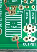
What you have looks fine. You should be able to just bend the wire as it enters the pcb so it moves the coil over and in alignment with the silkscreen. There is no need to measure it if you followed the instructions shown in the build guide and bom.First testcoil with a selfmade windingtool. Not perfect but the nextone will be a bit better I think. Also a bit close to the speaker output.
It does look like you have the wire going into the wrong hole though. Those holes are for people who want to run R127 through the centre of the inductor.
The correct holes are shown below. Not that it really matters. It just might make it easier for you as they are offset.
Attachments

I made it using the build guide instructions and then measured with a mid-level LCR (BK) it and it was spot on. A few tens or even 100 nH won't matter that much as it's designed to correct capacitive load impedance at high frequencies for stability. Truly nasty capacitive loads are uncommon with properly designed cross-overs unless you are playing with exotic tweeters. Lots of folks omit the output inductor with no problems while using reasonable speaker loads.
I have the EF3-3 boards and plan to mount de pcb parallel to the main heat sink. So I can either mount Q104 directly on the heat sink below the board, or on the closest output device using wired connections. Which option is the preferred one that gives the best thermal bias tracking ?
By the way, the Hfe for all my MJE340 measure around the not-very-impressive value of 70. I hope this is not an issue ?
By the way, the Hfe for all my MJE340 measure around the not-very-impressive value of 70. I hope this is not an issue ?
The theoretical answer is that on top of an output transistor is best - the least delay and closest to the junction. However, that said, I find my copy of the EF3-4 is way over compensated in that position. It might work better on the heat sink, as that would make the compensation more about the average temperature. I'm looking at the electronic change necessary to reduce the compensation slope and will report back when I have an update.
The present situation with Vbe on the output transistor will clearly make sure there is no thermal runaway, so it may not be a bad thing. I may just be nitpicking, as @fireanimal has data to say that at higher outputs, the WV is not very sensitive to bias point. I'm sort of hoping that he will post some data about distortion at say 1 to 5 watts output as that is where I understand Xover distortion is greatest. His measurements to date have been very encouraging about the quality of this design.
The present situation with Vbe on the output transistor will clearly make sure there is no thermal runaway, so it may not be a bad thing. I may just be nitpicking, as @fireanimal has data to say that at higher outputs, the WV is not very sensitive to bias point. I'm sort of hoping that he will post some data about distortion at say 1 to 5 watts output as that is where I understand Xover distortion is greatest. His measurements to date have been very encouraging about the quality of this design.
A couple of tries further down the road has led the way to an acceptable coil winding result. Boards close to a finish now. Only the driver heatsinks and then its on to the real challenge (for me) getting the power supply in place.

Hi Guy's,
The build guide was updated.
Current version is now 32. The first post and the Dropbox folder has been updated.
Revisions are noted in the revision section.
Thanks @wkloppen
The build guide was updated.
Current version is now 32. The first post and the Dropbox folder has been updated.
Revisions are noted in the revision section.
Thanks @wkloppen
I have tested this and by far the best position is mounted directly on the output transistor. I will try to get some low wattage frequency sweeps and different bias points, but I'm not convinced it will change much, as the temperature wont change much at low power anyhow.The theoretical answer is that on top of an output transistor is best - the least delay and closest to the junction. However, that said, I find my copy of the EF3-4 is way over compensated in that position. It might work better on the heat sink, as that would make the compensation more about the average temperature. I'm looking at the electronic change necessary to reduce the compensation slope and will report back when I have an update.
The present situation with Vbe on the output transistor will clearly make sure there is no thermal runaway, so it may not be a bad thing. I may just be nitpicking, as @fireanimal has data to say that at higher outputs, the WV is not very sensitive to bias point. I'm sort of hoping that he will post some data about distortion at say 1 to 5 watts output as that is where I understand Xover distortion is greatest. His measurements to date have been very encouraging about the quality of this design.
hello everybody
I'm gathering components to populate the EF3-3 boards with 60v rails.
I have noticed that Sanken drivers are more appreciated than MJEs.
I would like you to tell me where I can buy Sanken drivers, because they don't exist on the usual sites (Mouser, TME, RS, etc.).
Thanks.
Carlos
I'm gathering components to populate the EF3-3 boards with 60v rails.
I have noticed that Sanken drivers are more appreciated than MJEs.
I would like you to tell me where I can buy Sanken drivers, because they don't exist on the usual sites (Mouser, TME, RS, etc.).
Thanks.
Carlos
@fireanimal I realize I may be picking nits. The real test for this will be to test after warmup at low power, then heat things up with a high power run so the temperature rises by 15C or so. Then drop the output back to the low level and see what the distortion is compared to the earlier run before everything cools off. At least, this is what Cordell has recommended in his chapters on bias stability. The idea is to try to get the bias right at more than a single point. (temperature). If I could make the measurements that you are are making I'd gladly do this myself. I'm working on getting there, but the best I can measure with my current setup is .0003% due to my noise floor.
You guys must think the Wolverine is my full time job 😆
Just kidding. I will do my best within 1 week to get those results, I have some other things that I need to tend to first, then I can move onto that.
BUT Q104 Mounted Directly on the output transistor is the BEST option.
Just kidding. I will do my best within 1 week to get those results, I have some other things that I need to tend to first, then I can move onto that.
BUT Q104 Mounted Directly on the output transistor is the BEST option.
Cool, I got all the needed parts for the boards and now I'm waiting when my boards arrive 🙂 So exiting and so mutch to learn :SI built my Wolverine exactly with this configuration and it works like a charm!
Gaetano.
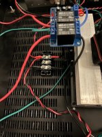
I was reading the build guide and other information in dropbox and I'm bit confused about wiring SMPS .
Could you please share some pictures of your amp SMPS wiring? It would help me a lot to understand all schematics what is in dropbox about wiring.
Thank you!
This is not a Wolverine, but the wiring should be very close. I took the Live and Neutral from the IEC input socket, Live goes to switch on front panel and then Live (after switch) and Neutral go to the bottom right hand side of the SMPS.
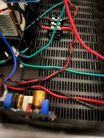
the Secondaries are all behind the heatsink and coded by heat-shrink in Black (Negative), Red (Positive) and Green (0) that goes to a "start ground bolt in the chassis.
the Positive and Negative go to a buss bar, Positive (Red) on the Left lug and Negative (Black) on the Right lug (both channels are stacked on a single lug.
Ground - I take a ground from the speaker ground, ground (0) from the SMPS and both Grounds (signal and Power) from the amplifier boards all go to the "Star Ground" lug connected to the chassis.
I was worried about the wiring, but the amp is the quietest one in my fleet, hum is so low I can barely hear it at night with my ear touching the woofer. The fan on the SMPS is the loudest thing the amp case and I can't hear it 2 feet away.
Hope my explanation and pictures help, but honestly an SMPS is the simplest and quickest way to have an amp singing.
Link to the SMPS - better pictures so you know the connection points better.
AliExpress 1200W SMPS +/-65V
Attachments
Nice V4H Bullittstang 😉
Does that SMPS have a standby circuit enabling the use of a low voltage switch to turn on the amp?
Does that SMPS have a standby circuit enabling the use of a low voltage switch to turn on the amp?
Hi Wkloppen,A couple of tries further down the road has led the way to an acceptable coil winding result. Boards close to a finish now. Only the driver heatsinks and then its on to the real challenge (for me) getting the power supply in place.
View attachment 1161376
Just a tip,
Scrape the enamel off the ends of the wire up to a point a little more than the top pcb pad and use a helping hand/crocodile clip holder to hold the coil then pre tin the lead ends with a fair bit of heat before soldering into the pcb.
Make sure there is no enamel left on the ends so you get very solid clean connections.
Also it is worth putting a little epoxy glue or super glue inside the coil once it is formed.
- Dan
Thx Dan....did exactly that except pre-ing the ends. The joints look fine thank god🙂...Used a bit of shoogoo to glue the inside bottom.Scrape the enamel off the ends of the wire up to a point a little more than the top pcb pad and use a helping hand/crocodile clip holder to hold the coil then pre tin the lead ends with a fair bit of heat before soldering into the pcb.
mhuth1776 and fireanimal - My simulator says the distortion at 1-5W is low. However, going to a 4 ohm load will double the distortion and maximum dissipation. Potential problems in thermal compensation will show up at 4 ohms.
Ed
Ed
Boards ready. PSU coming up. Diyaudiostore PSU boards not available so I have to find something else. Asked in other thread and somebody mentioned some boards of Thatcherdiyadio...anyone familiar with that or do I need to explore other options?

^ That was me. I made that suggestion (within context) that you were looking for something like the Universal PSU boards and you had stated your preference for mounted monolithic rectifiers from a certain company along with your preferred capacitors.
There are so many good options. First, you need to decide what type of power supply you want. It seems you want a linear supply vs. SMPS. Do you want it regulated? Do you want a 'traditional' CRC filter, a CLC filter a CRCLC filter ... etc. etc? More context will allow people to provide more precise recommendations for PCBs that will support your choices. From what I've read in this thread the PSRR of this amplifier is exceptional, so there should be some wonderful options.
FWIW, I'm leaning SMPS.
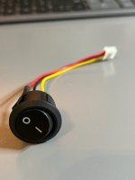
It came with a toggle switch, I re-wired the SMPS to always be on and then I can use the mains switch already in the chassis. Pic of the actual toggle switch, and only writing on it says 125V/250V @ 15A so I don't think the SMPS is designed to use a low power switch, but correct me if I'm wrong.Nice V4H Bullittstang 😉
Does that SMPS have a standby circuit enabling the use of a low voltage switch to turn on the amp?
Attachments
- Home
- Amplifiers
- Solid State
- DIY Class A/B Amp The "Wolverine" build thread