Hi Guy's,
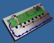
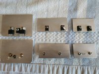
When planning your wiring layout you may want to consider a wiring layout like this. It avoids having your low impedance output wiring running close to you high impedance negative feedback trace and you high impedance signal input wires.
You can simply build a small bridge out of some light gauge aluminium and mount it to your heatsink.
Attachments

Nice tip Stuart. More holes to tap, joy 😳
On the subject of wiring, I seem to recall Tom C. once posting that it was a bad idea to put the PS of a power amp in a separate enclosure and connect it by an umbilical, but I can’t remember the reason. Maybe something to do with increased EMI ?
On the subject of wiring, I seem to recall Tom C. once posting that it was a bad idea to put the PS of a power amp in a separate enclosure and connect it by an umbilical, but I can’t remember the reason. Maybe something to do with increased EMI ?
When it comes to keeping input signal and output wiring separate, we literally can build a bridge and get over it!!!! 🙂 I might just try this approachHi Guy's,
When planning your wiring layout you may want to consider a wiring layout like this. It avoids having your low impedance output wiring running close to you high impedance negative feedback trace and you high impedance signal input wires.
You can simply build a small bridge out of some light gauge aluminium and mount it to your heatsink.
- Dan
I do the same. Though triedWhy didn't I think of that!!!!!!!
This cheap clamp from Amazon ebay Stuart posted is not wide enough to accommodate ef 3 boards. I agree that standoffs are the perfect alternative.Hi Guy, Talking about pcb holders. I find just using long pcb stand offs on either side of the pcb is good enough, in fact I prefer this method to using a pcb holder like shown below. I like just using stand offs because its quick and easy to flip and more importantly rotate the pcb to the exact orientation so you can get your soldering iron tip right in there and at the optimal angle to solder each joint.
I find the pcb holder to be great for flipping the pcb but its not very friendly when it comes to rotating the whole pcb board clockwise or anticlockwise as you have to rotate the entire pcb holder frame.
Anyway just my 2 cents on the subject. 🙂
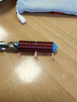
11.5mm former with 13turns 1.40 mm enamelled copper wire. Final coil size 14.5mm D x 19mm L.
I hope you don't mind this small difference.
I hope you don't mind this small difference.
Attachments
Last edited:
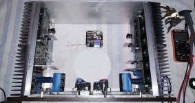
a small mock up preview for a smaller build 😗..2x Monoblock 150w thereabouts...57v rails...EF3 build...

I’d be interested to know which PS boards people have used . . .
to power one of my mono blocks
https://www.ebay.com.au/itm/165087648438
I believe it has to do more with increased supply impedance.Nice tip Stuart. More holes to tap, joy 😳
On the subject of wiring, I seem to recall Tom C. once posting that it was a bad idea to put the PS of a power amp in a separate enclosure and connect it by an umbilical, but I can’t remember the reason. Maybe something to do with increased EMI ?
In the years of my building I try hard to keep the PS in the same enclosure in my power amp builds with additional tidbits added like shielding, etc…to minimize the the length of the wire (while maximizing the gauge size) from the power supply board(s) themselves to the main circuit. I also try to make sure that the wiring from the primaries of said transformer or transformers are as short as possible which somewhat dictates the location of that transformer. Another option is to encase that entire section in its own sub enclosure within the main enclosure. These additional elements may make the difference during maxed out listening sessions where the amp has to instantaneously put out 100-200W, so there shouldn’t be an impediment from the power supply (which includes the PS wiring) when that occurs.
I know that isn’t necessarily the practice of the Class A fellas over on the Pass inspired forums but this is a Class AB amplifier with very little quiescent bias current (I would say more optimum quiescent bias current as dictated by THD spectra, etc…). From that perspective, I would endorse Tom C’s advice given that there are more parallels between his designs and this design than the Class A designs I’ve seen.
Shielding the toroid and potting it pretty much puts a damper on all strange extraneous noises in my experience. Only disadvantage is cost. So EMI is addressed as well. That’s what I do anyway. Throw money at the problem! That being said the circuit we are discussing here has probably incredible PSRR (and CMRR) specifications which means it’s trying hard to be immune to said perturbations in the power supply.
Just an opinion ;-)
Best,
Anand.
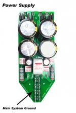
I had a spare 'bespoke' pcb left over from an old Gainclone build, so I used that with all components uprated accordingly. Not a very good photo I'm afraid ...I’d be interested to know which PS boards people have used . . .
Attachments
The best way to eliminate hum is to use a shielded transformer with shielding between the primary and secondary. The shielding must be connected to the housing and to the ground. This reduces the stray capacitance considerably.

Hi diyralf,Why aren't the transistors mounted on the main heatsink?
One approach to temperature compensating an Emitter Follower Triple (EF3) is to place all three pairs (pre-drivers/drivers/outputs) on the main heatsink along with one device of the bias spreader. In this case, all devices will essentially be at the same temperature and therefore compensated as a whole.
Another approach such as the one one used in the Wolverine design, is to separate the outputs devices from the pre-driver/drivers and track them individually. The bias spreader can be constructed using two transistors such as a Darlington pair with each device mounted separately on the respective heatsinks of the driver and output devices. This can provide better bias stability as the two groups are more accurately tracked. It also allows the drivers to run at their own temperature rather than be subjected to that generated by the output devices which can be much substantially higher.
Both methods are equally valid and is ultimately a design choice. Personally, I prefer the separated driver/output temperature compensation and think it has been really well executed in the Wolverine design. Cheers.
Paul
Hi my friends.
I m ready to order parts from Mouser and BanzaiMusic
I want your HELP!!!.
Is this combination OK for 4 ohm load Speakes and +- 70V power supply?
I m using 6 output transistors version of PCB.
Pre Driver: 2SC3503E and 2SA1381E
Driver: MJE15032 and MJE15033 or 2SC3503E and 2SA1381E
Outputs: 2SC5359 - 2SA1987 TOSHIBA
Similar questions came to my mind and I kindly ask the team for an advice:
- In the sheet 2 of the BOM: Why are there different voltages for linear supplies and SMPS within one line? Is it because the voltages that were actually tested were slightly different for the different supplies?
- For my concrete case: I have an 800W/60V SMPS with NJW0281/0302 outputs and MJE1503X drivers on an EF3-3. Would you consider this a reasonable configuration?
Hi my friends.
I m ready to order parts from Mouser and BanzaiMusic
I want your HELP!!!.
Is this combination OK for 4 ohm load Speakes and +- 70V power supply?
I m using 6 output transistors version of PCB.
Pre Driver: 2SC3503E and 2SA1381E
Driver: MJE15032 and MJE15033 or 2SC3503E and 2SA1381E
Outputs: 2SC5359 - 2SA1987 TOSHIBA
Pre Drivers are ok, MJE Drivers are OK the 3503/1381 are not used for drivers. Outputs I would say NO, I have used MJL4281/MJL4302 on 71v EF3-3 and no issues.
- Home
- Amplifiers
- Solid State
- DIY Class A/B Amp The "Wolverine" build thread