Regards my last post Guys - only used bold text to differentiate my replies from Stuart's recommendations! Not to be taken as me 'shouting', which is sometimes taken out of context - so if it did come over that way to anyone, my sincere apologies, not intended!
Thanks
Thanks

@richbandit : I’ve never heard a MyRef amp but I have another LM3886 amp, the Neurochrome. To give your comments more meaning for me, have you compared the MyRef to any of Tom’s amps?
Well if they truly are comparable then based on your experience that makes the Wolverine one hell of an amp . . . .Hi @Studley,
'fraid not, never listened to a Neurochrome myself. Some posts on the My_Ref Fremen Build thread have said it's comparable to the Modulus-86, but this is hearsay, I can't substantiate that comment.
It certainly is!Well if they truly are comparable then based on your experience that makes the Wolverine one hell of an amp . . . .
I've just been listening to a session playing Snowy White (for those who haven't heard of him, less well known but very well respected British guitarist, roots in blues but associated with plenty of big names - Pink Floyd, Thin Lizzy, more recently Roger Water's band, and more ...). Hearing things leap out at me I'd not heard before, such fine detail hiding in the music that I've obviously been missing all these years. And I thought it was my aging ears ...!
A little story - back in the 1980's, at the time being flush with cash during a prolonged stint working in Middle East, I bought a full top-of-the-range Marantz component system in 'champagne gold', which included their classic PM-45 amp and superb LS-15A speakers. I listened to everything in the shop in different combinations, and this set up sounded by far the best, so I bought it. It was the best sounding amp/speaker combo I'd ever heard and was sad to see it go a few years ago (speakers too big for room, forced to downsize!).
I know years (and ears!) might play tricks over time, but, so far, I can truly say that the Wolverine actually betters how the Marantz sounded. There, I've said it!
I'm a very happy bunny!
PS: update re: my 'hum' issue - it's really not going to be a problem for me; I need to place my ear right up against the speaker to hear anything at all and even then it's hardly discernible, so not worth worrying about. Given the superb sound quality of the amp 'as is' I think I'll leave well alone and I can happily live with that. But, at some point I'll certainly investigate Stuart's suggestions and see if it improves things.
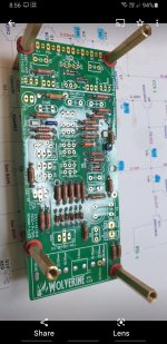
Hi Guy, Talking about pcb holders. I find just using long pcb stand offs on either side of the pcb is good enough, in fact I prefer this method to using a pcb holder like shown below. I like just using stand offs because its quick and easy to flip and more importantly rotate the pcb to the exact orientation so you can get your soldering iron tip right in there and at the optimal angle to solder each joint.
I find the pcb holder to be great for flipping the pcb but its not very friendly when it comes to rotating the whole pcb board clockwise or anticlockwise as you have to rotate the entire pcb holder frame.
Anyway just my 2 cents on the subject. 🙂
I find the pcb holder to be great for flipping the pcb but its not very friendly when it comes to rotating the whole pcb board clockwise or anticlockwise as you have to rotate the entire pcb holder frame.
Anyway just my 2 cents on the subject. 🙂
Attachments

IPL Acoustics M1tlm transmission lineYes I‘m familiar with Snowy White. Really good! What are your speakers?
Hi Stuart,
Many thanks for your comments, suggestions and advice! I'll try some of your tips when I can.
Richard
Hi Richard, thanks for your detailed response. From what you explained it does sound like the noise is coming in on you RCA cable and not something that is happening inside your chassis due to your wiring or the wolverine amplifier modules.
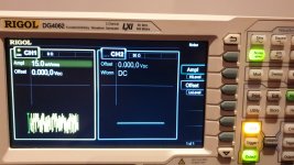
For completeness yesterday I did do some testing.
I found that injecting 1mv of noise from my signal generator was audible from my tweater with my ear approximately 5cm from the tweaker. The sensitivity of your speakers will also affect this number. My speakers have a sensitivity of 90dB
I then repeated the test at 1 meter from the tweeter. I needed 4mV of noise to be able hear anything.
I then had @danieljw measure one of his completed Wolverine amp modules to see what the AC measurement was. With the input terminal shorted at the ips board he measuring 80 micro volts from the output terminal to the speaker return terminal. 🙂🙏
So if you measure your AC voltage at your speaker outputs, at the binding posts or at you speakers binding posts a value of 1mV or less should be ok. It would be interesting to know what you have so please measure and post your value.
I will update the build guide with those numbers so a basic test can be done while preforming the initial testing of the wolverine amp modules.
Once again I happy that your enjoying your new Wolverine build.
Attachments
Question.
I see pretty much everyone opted for wima @ C1, and I have Panasonic ECW ones ordered.
I have another order to do, so am considering if I should actually go for those MKP caps instead?
I see pretty much everyone opted for wima @ C1, and I have Panasonic ECW ones ordered.
I have another order to do, so am considering if I should actually go for those MKP caps instead?
Hi Stuart,Hi Richard, thanks for your detailed response. From what you explained it does sound like the noise is coming in on you RCA cable and not something that is happening inside your chassis due to your wiring or the wolverine amplifier modules.
For completeness yesterday I did do some testing.
I found that injecting 1mv of noise from my signal generator was audible from my tweater with my ear approximately 5cm from the tweaker. The sensitivity of your speakers will also affect this number. My speakers have a sensitivity of 90dB
I then repeated the test at 1 meter from the tweeter. I needed 4mV of noise to be able hear anything.
I then had @danieljw measure one of his completed Wolverine amp modules to see what the AC measurement was. With the input terminal shorted at the ips board he measuring 80 micro volts from the output terminal to the speaker return terminal. 🙂🙏
So if you measure your AC voltage at your speaker outputs, at the binding posts or at you speakers binding posts a value of 1mV or less should be ok. It would be interesting to know what you have so please measure and post your value.
I will update the build guide with those numbers so a basic test can be done while preforming the initial testing of the wolverine amp modules.
Once again I happy that your enjoying your new Wolverine build.
Many thanks for your further details and suggestions.
To clarify once more - with nothing at all plugged into RCA sockets, hum is present, so the issue is definitely manifesting itself inside the chassis. If I then remove the wires from the IPS board input terminals, hum disappears completely - dead quiet, so amp board itself is absolutely quiet, no problem. The only thing then left that can possibly be causing this is the short piece of screened cable (on the LH channel, anyway) from RCA socket terminals to input terminals on IPS, which therefore seems to be picking up something, from somewhere. The I/P cable route to RH channel is longer (to try to avoid any potential ground loops), and I can confirm that the hum in RH speaker is just ever so slightly louder. So yes, the issue definitely seems to be related to the cable from RCA to inputs picking up this interference. Bizarre!
As I've now mentioned, it's such a small thing that it's not going to be a problem for me, just annoying knowing it's there! I can, of course, easily get to my speaker binding posts so yes I'll measure the AC when in 'idle' and report back. What's not so easy now is to remove the amplifier to get inside it to short or disconnect inputs - but I'll see what I can do.
Speaker sensitivity is 87dB by the way ...
Once again, many thanks for your assistance.
There are two schools of thought regarding the input cap. One says that the cap changes the sound and the other says the opposite.Question.
I see pretty much everyone opted for wima @ C1, and I have Panasonic ECW ones ordered.
I have another order to do, so am considering if I should actually go for those MKP caps instead?
Some builders eliminate the cap completely and use a wire link.
It's up to the builder to decide what to use in that position. This is why I have used many options in the BOM.
The cap that you have selected is of good quality. Start with that and experiment.
Just a quick note on this,Hi Richard, thanks for your detailed response. From what you explained it does sound like the noise is coming in on you RCA cable and not something that is happening inside your chassis due to your wiring or the wolverine amplifier modules.
For completeness yesterday I did do some testing.
I found that injecting 1mv of noise from my signal generator was audible from my tweater with my ear approximately 5cm from the tweaker. The sensitivity of your speakers will also affect this number. My speakers have a sensitivity of 90dB
I then repeated the test at 1 meter from the tweeter. I needed 4mV of noise to be able hear anything.
I then had @danieljw measure one of his completed Wolverine amp modules to see what the AC measurement was. With the input terminal shorted at the ips board he measuring 80 micro volts from the output terminal to the speaker return terminal. 🙂🙏
So if you measure your AC voltage at your speaker outputs, at the binding posts or at you speakers binding posts a value of 1mV or less should be ok. It would be interesting to know what you have so please measure and post your value.
I will update the build guide with those numbers so a basic test can be done while preforming the initial testing of the wolverine amp modules.
Once again I happy that your enjoying your new Wolverine build.
The leads leads to the bench multimeter were approximately 1 meter long twisted leads and the multimeter meter was not nulled or zeroed prior so it it is likley less than this number.
Hope this information is useful.
- Dan
I am using Solen MKP-FC 400Vdc, but only because I have had them on hand for ages (their date code is 1982)Question.
I see pretty much everyone opted for wima @ C1, and I have Panasonic ECW ones ordered.
I have another order to do, so am considering if I should actually go for those MKP caps instead?
Thanks Dan, noted ....Just a quick note on this,
The leads leads to the bench multimeter were approximately 1 meter long twisted leads and the multimeter meter was not nulled or zeroed prior so it it is likley less than this number.
Hope this information is useful.
- Dan
Well, a bit of an epic fail, I'm afraid!
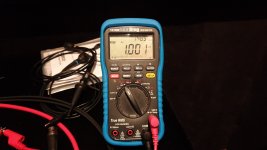
Went to check AC at binding posts on speakers (as access to rear of amp now difficult), using my trusty old hand-held meters (2 different models), to realise that they're only really intended to measure higher (e.g., mains levels, etc.) AC voltages - smallest AC scale is up to 200 volts!!! So as expected both meters read 0.00 AC volts on binding posts, no doubt because they're simply unable to measure anywhere near the required mV level needed ..... Sadly don't have access to better meter(s) or 'scope, etc.
So, sorry Guys, unable to add any more info to this one!
During testing, I disconnected the RCA leads at DAC end, which I could easily get to - which are Audioquest Golden Gate, 0.6m, so reasonable quality - and noticed that the hum was increased quite a bit by doing so. Reconnect the leads and hum reduced to (the as before) almost undiscernible level (DAC was powered, but turned off all this time). The hum really is so low that I'll definitely not worry about it anymore now. Meters showed the same (useless!) reading of 0.00 AC volts whether RCA's connected or not.
If/when I have the need to pull the amp out again I'll certainly pursue this further, just not sure when that might be. It definitely sounds like 50Hz, so at this moment I might suspect my power / transformer could be radiating it (to be fair, it's only a 'bog-standard' off-the-shelf transformer, nothing particularly special), so perhaps I'll try some shielding around that?
Only sorry I wasn't able to provide this great community with any more sensible information on the matter.
Thanks to all for your help, but please don't fret about this anymore - I'm not, I'm enjoying listening to the great sounds!
Richard
Hi Guy's.
I just updated the build guide.
The latest version is now 27.
Revisions noted at the end of the document.
Please use your Dropbox links to download the latest version.
I added a point regarding checking the AC voltage on the output.
Hopefully this will never be an issue for anyone, but at least taking a measurement early may save time troubleshooting a noise related problem later. It also serves as a benchmark for when you finalise the wiring layout in your chassis.
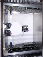
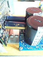
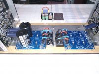
Small progress.
The distance between the PSU boards and positive negative entry spots of Volverine EF3 is about 4-6 cm...
The distance between the PSU boards and positive negative entry spots of Volverine EF3 is about 4-6 cm...
Attachments
Last edited:
Why didn't I think of that!!!!!!!Hi Guy, Talking about pcb holders. I find just using long pcb stand offs on either side of the pcb is good enough, in fact I prefer this method to using a pcb holder like shown below. I like just using stand offs because its quick and easy to flip and more importantly rotate the pcb to the exact orientation so you can get your soldering iron tip right in there and at the optimal angle to solder each joint.
I find the pcb holder to be great for flipping the pcb but its not very friendly when it comes to rotating the whole pcb board clockwise or anticlockwise as you have to rotate the entire pcb holder frame.
Anyway just my 2 cents on the subject. 🙂
I had the same reaction!🙄Why didn't I think of that!!!!!!!
- Home
- Amplifiers
- Solid State
- DIY Class A/B Amp The "Wolverine" build thread