Great Idea, I did the same thing with the my Honey badger build.
You can check it out here if you like.
Honey Badger build
There is a video and a 3D model there too.
If I was to do it again which I will for my Wolverine build I will have the amplifier inputs at the rear and the power supply at the front of the case.
Good luck with your layout, a 3D model is the best way to optimise space.
Last edited:

I ordered a couple of PSU Boards, designed by @prasi . They are intended to be set up as CRC supply but i am intending to short all the filter resistor positions with jumper wire to achieve an almost only C supply. I like this design, because it offers everything i need: directly integrated bridge rectifiers, the possibility to snubber the transformer secondaries, solder pads for LEDs and enough faston terminal positions. Its also very small, only 100mm by 100mm. The SIP Bridges will be bolted under the PCB directly to the base plate of the enclosure. That way i will save even more space. I hope to squeeze two Antek AS-4445 and two of this boards into my 4U 300mm dissipante deluxe case.
I have some additional boards to give away for a small price to fellow DIYers inside the EU. Please hit me up via PM.
Thread about Prasis CRC supply on diyaudio
Order your own PCBs through pcbway.com

I have some additional boards to give away for a small price to fellow DIYers inside the EU. Please hit me up via PM.
Thread about Prasis CRC supply on diyaudio
Order your own PCBs through pcbway.com
Excellent psu boards AD! I’ve used them in a few builds. You can easily use Prasi’s SMD LT4320 active rectification boards (no heatsinking necessary) in the SIP bridge rectifier locations. (2 active rectifier’s required for this option)
Will you consider shipping to the uk?I ordered a couple of PSU Boards, designed by @prasi . They are intended to be set up as CRC supply but i am intending to short all the filter resistor positions with jumper wire to achieve an almost only C supply. I like this design, because it offers everything i need: directly integrated bridge rectifiers, the possibility to snubber the transformer secondaries, solder pads for LEDs and enough faston terminal positions. Its also very small, only 100mm by 100mm. The SIP Bridges will be bolted under the PCB directly to the base plate of the enclosure. That way i will save even more space. I hope to squeeze two Antek AS-4445 and two of this boards into my 4U 300mm dissipante deluxe case.
I have some additional boards to give away for a small price to fellow DIYers inside the EU. Please hit me up via PM.
Thread about Prasis CRC supply on diyaudio
Order your own PCBs through pcbway.com
View attachment 1102461
Yes I would, but the shipping costs to UK are on the high side. It's about €7,- for a big international letter, and about €13,- for a tracked parcel. Maybe some fees or UK VAT will be added by UK customs. That's why I said "EU only".. But if you still want some boards drop me a PMWill you consider shipping to the uk?
Thanks. I get home and read the thread of the PSU board.
May I ask what people use for pre-amplification with the amp?
Need to decide on what to use and build pre before I undertake the wolverine assembly.
May I ask what people use for pre-amplification with the amp?
Need to decide on what to use and build pre before I undertake the wolverine assembly.
Personally, I only use a DIY B1 Buffer, because my phono preamp has enough gain to drive my (low-gain) first Watt Amps. The Wolverine has 26 dB gain IIRC. For me and my speakers that's enough gain.
What kind of preamp you might need or not depends on the components you want to connect before and after your Amp, e.g. sources and speakers.
What kind of preamp you might need or not depends on the components you want to connect before and after your Amp, e.g. sources and speakers.
I am building a system from scratch, so plenty of freedom here. I don't think I need gain, passive could be fine. Used to have b1 before. Might want to try smtg different
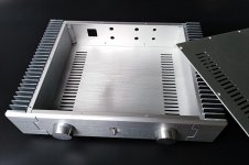
What is the requirement for heat dissipation and size of heatsinks? I am looking for alternatives to modushop- with some cute Chinese chassis around 90-120 mm in height available. I haven't seen anyone with a chassis smaller than 3U yet. The attached image is an example.
Attachments
You showed us a 3D drawing a few posts ago, surely that will inform you about the fit and height requirements of all your components. Then think about drilling and tapping the heatsink holes - they need to be very accurate - are you able to do this? If the stuff you want inside will fit then a case around 100mm high internally should be OK for temperature rise but this depends on the heatsink specifications. Black would be much better of course. Bigger is better too, keeps everything cool, much safer.
I am more curious about the temperature than fit this time around. I don't want to pick a chassis which will be useless in terms of heat dissipation.
Then select a large chasis and heat sinks with heat resistance lower than 0.3 K/W. Keep this board in cool and spacious chasis. As I can recall, you intend to put the preamp in the same chasis. You will need enough space to hurl everything into a single chassis.I am more curious about the temperature than fit this time around. I don't want to pick a chassis which will be useless in terms of heat dissipation.
Thanks. I have several options, I understand implications of stuffed enclosures. Thanks for the 0.3 k/w valueThen select a large chasis and heat sinks with heat resistance lower than 0.3 K/W. Keep this board in cool and spacious chasis. As I can recall, you intend to put the preamp in the same chasis. You will need enough space to hurl everything into a single chassis.
You're welcome voxxonline
Chasis, heat sinks and transformers along with large capacitors dominate the cost of an amplifier but we are building an extraordinary amplifier so let it look pleasing and cool. 😎
Chasis, heat sinks and transformers along with large capacitors dominate the cost of an amplifier but we are building an extraordinary amplifier so let it look pleasing and cool. 😎
Last edited:
Hello @Gianluca, are the 3U heatsinks drilled in a way that the PCBs can be mounted in parallel to the heatsinks?Hello guys,
I've just returned from BAF and as promised I've added the "substitution" for the Wolverine heatsinks in all our Dissipante 3U 400 chassis to make it easier to purchase them https://modushop.biz/site/index.php?route=product/product&product_id=811
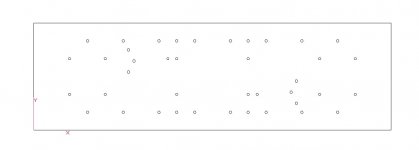
This is how we drill the heatsinks. The two 200mm heatsinks are drilled and held together by a bracket to avoid tolerance problems as kindly suggested by @stuartmp some time ago.
Attachments
Thank you, @Gianluca for the explanation!
I think I have to ask more precisely: If I want to mount the PCBs on the 3U heatsinks like here:
https://www.diyaudio.com/community/...he-wolverine-build-thread.385920/post-7027432
Then my question is: Are the holes in a high enough position so that the PCBs do not touch the bottom of the case?
I think I have to ask more precisely: If I want to mount the PCBs on the 3U heatsinks like here:
https://www.diyaudio.com/community/...he-wolverine-build-thread.385920/post-7027432
Then my question is: Are the holes in a high enough position so that the PCBs do not touch the bottom of the case?
Yes, I lay'd out all the holes for the 3U, 4U and 5U chassis and supplied them to Gianluca.Thank you, @Gianluca for the explanation!
I think I have to ask more precisely: If I want to mount the PCBs on the 3U heatsinks like here:
https://www.diyaudio.com/community/...he-wolverine-build-thread.385920/post-7027432
Then my question is: Are the holes in a high enough position so that the PCBs do not touch the bottom of the case?
From memory the only restriction with the 3U case is the output transistor package. You are limited to using a TO-3P transistors like the NJW0281G / NJW0302G
All the hole dimensions are in the build guide and a dxf file showing all the holes is in the Dropbox folder.
Thank you, @stuartmp - this was the information which I was looking for 👍
I think the pcb dimensions were the missing peace here 😉
I think the pcb dimensions were the missing peace here 😉
- Home
- Amplifiers
- Solid State
- DIY Class A/B Amp The "Wolverine" build thread