Hello WHG,
You are right, the red line I drawn is not exactly at the place I should I had draw it. But at the exit of the WE555 (I own a pair), the flair angle is so small that St will not change a lot if we take the reference few millimeters above or down.
There is 2 different aspects on how to consider the compression cavity (and the slits/ducts):
.
1) the low pass filter aspect
2) the efficiency aspect.
When sound flows from diaphragm too exit, to investigate the low-pass filter efefct , we probably have to take in account the entire volume between the diaphragm and the cross section for which the ducts have minimum total cross section area.
But for efficiency analysis we have to take in account the ratio between the pressure at the diaphragm and at the exit.
Best regards from Paris, France
Jean-Michel Le Cléac'h
The area of the horn joint is not where [St] is measured.
[St] is the area of the annular slit at the perimeter of the diaphragm for the example shown. The rest of the phase plug implements the beginning of horn flare.
Regards,
WHG
Last edited:
Hello Bill,
I disagree with the choice you have made in order to define the constriction.
On a cross section schematic it is difficult to estimate the total area of an annular shape (the radius to the axis have to be taken in account).
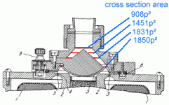
As an example, if we take the WE555 schematics, and consider 4 cross section of the ducts linking the exit to the diaphragm. (See the red lines in the attached figure)
According to your definition the constriction is more important on the lowest cross section. But now let's calculate the annular areas!
What we obtain is that the smallest annular area (908 square pixels) is obtained un the uppest cross section. We have to put the end of the compression cavity there.
Best regards from Paris, France
Jean-Michel Le Cléac'h
But shouldn't they in fact be calculated as diaphragm area divided by the area of the aperture(s) at the point(s) of greatest constriction? I have marked the apparent points of max constriction below.
Attachments
Last edited:
Some Thuras/Horn Issues
Truras Driver
A diaphragm of this size, without spiders to stabilize the voice coil, will exhibit rocking modes at wave lengths comparable to diaphragm diameter.
The camel humps between the voice coil and the compliance are intended to suppress these modes. If a redesign is anticipated, recommend spiders be added.
Bass Horns
For a horn, redesign of an EV Pat IV would do a better job in a room corner for the 'all-horn system at-home' venue. See Bentwood [1] for one approach to a K-Horn rework. The "Dope from Hope" got it right, and his Jubilee demonstrates that there still is room for improvement.
[1] bentwoodhorns.com
For bass reproduction perfection, in any small to medium sized enclosure, judicially placed servo controlled and equalized subs, al la Velodyne et al, is an effective and practical solution. Here distortion products can be held below 1% at 16 Hz, and room modes can be addressed, at any level the room can sustain without being shaken apart. I just do not see a compelling need to sacrifice the last musical octave for the sake of bragging rights of an all-horn system. Maybe a marriage is possible; if so, it will be out of room corners, not elsewhere, unless of course the horn is the room.
In closing, only the U.S. Army does it better.
Regards,
WHG
Attachments
Hello Bill,
I disagree with the choice you have made in order to define the constriction.
That's fine. I just eyeballed it, and I could very well be wrong about the exact locations of the cross-section minima. It's the principal of how compression ratio is figured that's important.
Over and over, I see people posting about how a 2" compression driver is better than a 1.5" model because, *obviously,* it has a lower compression ratio. But in fact, the two drivers by a given manufacturer they're comparing often have exactly the same compression ratio, because they use the exact same phasing plug whose slits define the minimum cross section. The only relevant difference between the two drivers often is that one has an extended throat added that flares from 1.5" to 2"! 🙂
Right-On!
The location and dimensions of the joint between the driver and the horn is arbitrary and acoustically unimportant. On the other hand, the size (diameter) of the diaphragm is important as it is the fundamental determinant of volume displacement and the onset of standing wave modes in the diaphragm and surrounding cavities as well. Typically, the compression ratio is set at 10:1 except for drivers operated appreciably below 500 Hz, of which there are precious few.
Regards,
WHG
That's fine. I just eyeballed it, and I could very well be wrong about the exact locations of the cross-section minima. It's the principal of how compression ratio is figured that's important.
Over and over, I see people posting about how a 2" compression driver is better than a 1.5" model because, *obviously,* it has a lower compression ratio. But in fact, the two drivers by a given manufacturer they're comparing often have exactly the same compression ratio, because they use the exact same phasing plug whose slits define the minimum cross section. The only relevant difference between the two drivers often is that one has an extended throat added that flares from 1.5" to 2"! 🙂
The location and dimensions of the joint between the driver and the horn is arbitrary and acoustically unimportant. On the other hand, the size (diameter) of the diaphragm is important as it is the fundamental determinant of volume displacement and the onset of standing wave modes in the diaphragm and surrounding cavities as well. Typically, the compression ratio is set at 10:1 except for drivers operated appreciably below 500 Hz, of which there are precious few.
Regards,
WHG
A diaphragm of this size, without spiders to stabilize the voice coil, will exhibit rocking modes...
Excellent point! This is a problem a lot of dome midranges historically had. When a diaphragm of any significant mass is anchored on only one plane, it is vulnerable to rocking modes. This is why ATC, for one, goes to the trouble of anchoring the moving parts of their SM75-150 dome mid with two axially spaced surrounds.
May be a good idea to tweak the Thuras design a bit on this point, in addition to the magnetic circuit points JMMLC brought up earlier.
Last edited:
<ignorance alert> what is Fe Si (NO) is that "not oriented" whereas the (GO) is grain oriented??
Then the next question is why would "GO" be better than (NO) (or iron) for transformer lams?
And, as far as getting pure iron, we're not talking "cast iron", but ductile iron??
Seems like iron ought to be available... somewhere...???
And then Goto is not using iron, I would assume...
curiouser and curiouser said Alice.
_-_-bear
Hello,
Let's do the compression ratio estimation for the WE555.
The ratio between the active diameter of the diaphragm and the active diameter of the troat of the attached horn is 2.84, thus the comrpession ratio is (2,84)² = 8.
See attached graph
Best regards from Paris, France
Jean-Michel Le Cléac'h
Maybe a minor issue, but does the outside area of the diaphragm suspension really radiate, and should it be included in the calculation? If it does not really contribute then the compression ratio would somewhat reduced??
_-_-bear
Edit: but the other thing that comes to mind with the 555 is that I have read WE journal articles where they tested the 555 down to 75Hz.! (plane wave tube) In that article they had to run the plane wave tube out the window of the lab to make it long enough!! 😀
Edit II: Jack how does the current look when you use 300v and thinner wire for the field coil? I know that some older field coil drivers used the B+ voltage of the amp's PS on the FC...
Edit III: Jmmc, from whence cometh that nice magnetic FEMM software??
Last edited:
What we obtain is that the smallest annular area (908 square pixels) is obtained un the uppest cross section. We have to put the end of the compression cavity there.
Jean-Michel,
Just a little point, but I'm still curious about why you are measuring annular area in a plane that is not normal to the direction of pressure wave travel.
Looking at the cross section of the 555, it seems to me that pressure waves are converging during their passage across the phasing plug, and their inner edges would not be coplanar with their outer edges.
Edit II: Jack how does the current look when you use 300v and thinner wire for the field coil? I know that some older field coil drivers used the B+ voltage of the amp's PS on the FC...
2 Amperes, 100V, 25W, 2T, AWG21 four coils, 2000 turns, 1.3km, over 5kg Cu.
Now 3x voltage and half of wire thickness means ca. five times less current needed and four times more power.
2 Amperes, 100V, 25W, 2T, AWG21 four coils, 2000 turns, 1.3km, over 5kg Cu.
Now 3x voltage and half of wire thickness means ca. five times less current needed and four times more power.
Clearly I do not understand. More power?? More power available magnetically??
More turns for certain... I expect, due to thinner wire.
_-_-bear
Yes
At the outer edge of the surround there is no excursion, at the inner edge it is equal to that of the adjoining diaphragm. The effective radiating diameter is therefore equal to the diaphragm diameter plus slightly less than the width of the surround. Volume displacement may thus be represented by a truncated cone, where
[Rd] - Diaphragm Radius
[Ws] - Suspension Width
[Rs] - Surround Radius
= [Rd]+[Ws] {1}
[Ed] - Diaphragm Excursion (Height)
then Volume Displaced
[Vd] = [Sd]*[Ed]= 1/3 [pi]*([Rd]^2+[Rd]*[Rs]+[Rs]^2)*[Ed] {2}
and the Effective Radiating Area
[Sd] = (1/3)*[pi]*(([Rd]^2)+([Rd]*[Rs])+([Rs]^2)) {3}
Subtituting {1} in {3}
[Sd] = [pi]*(([Rd]^2) + ([Ws]*[Rd]) +([Ws]^2)/3) {4}
Regards,
WHG
Maybe a minor issue, but does the outside area of the diaphragm suspension really radiate, and should it be included in the calculation? If it does not really contribute then the compression ratio would somewhat reduced??
_-_-bear
At the outer edge of the surround there is no excursion, at the inner edge it is equal to that of the adjoining diaphragm. The effective radiating diameter is therefore equal to the diaphragm diameter plus slightly less than the width of the surround. Volume displacement may thus be represented by a truncated cone, where
[Rd] - Diaphragm Radius
[Ws] - Suspension Width
[Rs] - Surround Radius
= [Rd]+[Ws] {1}
[Ed] - Diaphragm Excursion (Height)
then Volume Displaced
[Vd] = [Sd]*[Ed]= 1/3 [pi]*([Rd]^2+[Rd]*[Rs]+[Rs]^2)*[Ed] {2}
and the Effective Radiating Area
[Sd] = (1/3)*[pi]*(([Rd]^2)+([Rd]*[Rs])+([Rs]^2)) {3}
Subtituting {1} in {3}
[Sd] = [pi]*(([Rd]^2) + ([Ws]*[Rd]) +([Ws]^2)/3) {4}
Regards,
WHG
Bill,
As a teacher, for pedagogical purposes, I often try to keep the thing I want to explain in a simple manner (KISS), but I try also to not outrageously simplify.
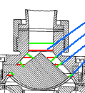
You'll see here attached a graph with the isopressure lines in the ducts of the WE555 coloured in green. A simple geometrical consideration will demosntrate easily that the calculation performed using the "red lines" will lead to similar results than the calculation performed using the "greeen lines" .
(Additionally I would say that for the measurement of the annular areas in square pixels I use PaintShop pro that can only give me the horizontal and vertical dimensions in pixels of the selectionned areas...)
Best regards from Paris, France
Jean-Michel Le Cléac'h
Jean-Michel,
Just a little point, but I'm still curious about why you are measuring annular area in a plane that is not normal to the direction of pressure wave travel.
Looking at the cross section of the 555, it seems to me that pressure waves are converging during their passage across the phasing plug, and their inner edges would not be coplanar with their outer edges.
Attachments
Last edited:
Hello Bear,
Yes, the outer part of the diaphragm partcipate to the radiation too. When the WE555 was designed, it was still difficult to manufacture a phase plug having many concentrical slits. To help the driver to reproduce higher frequency we have to keep equal the pathlength form the different radiating zones. Harrison and others at Bell lab choose to use a simple phase plug, facing the inner part of the whole diaphragm and additionally they choose a complex shape of the diaphragm in order to keep equal the pathlength from the outer part of the diaphragm and the inner part of the diaphragm. Doing this the WE555 could reproduce frequencies above 5kHz.
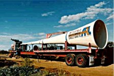
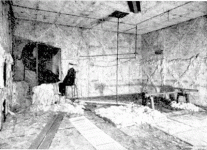
You'll see on the attached picture taken in the anechoic room at Bell lab, on left a test of a compression driver (probably WE555W) on a WE15A horn. On right of the picture you can see a compression driver in test attached to the planar wave tube 30meter long (it pass through the wall and go out the anaechoic room) used by Thuras and Wente to develop the WE555 and WE594 comrpession drivers. Near the end of the tube attached to the driver, a small hole received the calibrated electrostatic microphone designed by Wente (see Physical review 1917) which allows absolute pressure measurements and replaced the thermiophone invented by Webster which was used previously to perform absolute pressure measurements.
The magnetic finite elements software FEMM may be download fro free at:
http://www.femm.info/wiki/HomePage
Best regards from Paris, France
Jean-Michel Le Cléac'h
Maybe a minor issue, but does the outside area of the diaphragm suspension really radiate, and should it be included in the calculation? If it does not really contribute then the compression ratio would somewhat reduced??
_-_-bear
Edit: but the other thing that comes to mind with the 555 is that I have read WE journal articles where they tested the 555 down to 75Hz.! (plane wave tube) In that article they had to run the plane wave tube out the window of the lab to make it long enough!! 😀
Edit II: Jack how does the current look when you use 300v and thinner wire for the field coil? I know that some older field coil drivers used the B+ voltage of the amp's PS on the FC...
Edit III: Jmmc, from whence cometh that nice magnetic FEMM software??
Attachments
Last edited:
More power?? More power available magnetically?? More turns for certain... I expect, due to thinner wire.
Electrical power - Ohm's law. One must balance required power, voltage and amount of copper. 2000-3000 turns are enough. This all means you need 0,5-1,0mm wire, 5-10kg of copper and clean power supply so that hum noise is kept low. I'm new to field-coils and can be wrong of course.
Hello,
Here is a picture (you probably yet saw) of a 4inches Goto bass loudspeaker:
http://2.bp.blogspot.com/_Nw4pZg3f-.../f3ITtGlhLGM/s400/Goto_4Inch_BassDriver_2.jpg
see also
http://rarehifi.com/wp-content/uploads/2010/10/digitalizar0009.jpg
and
http://www.goodsoundclub.com/Site_Images/DSC_73601.JPG
http://www.goodsoundclub.com/Site_Images/d1250.bmp
http://www.goodsoundclub.com/Site_Images/yl 75000 2.JPG
No phase plug is used for what it seems and a low compression ratio.
Best regards from Pairs, France
Jean-Michel Le Cléac'h
Last edited:
Pythagoras to the Rescue
In the phase plug annulus [gpix]=[rpix]/[2^(1/2)]
Regards,
WHG
Bill,
As a teacher, for pedagogical purposes, I often try to keep the thing I want to explain in a simple manner (KISS), but I try also to not outrageously simplify.
You'll see here attached a graph with the isopressure lines in the ducts of the WE555 coloured in green. A simple geometrical consideration will demosntrate easily that the calculation performed using the "red lines" will lead to similar results than the calculation performed using the "greeen lines" .
(Additionally I would say that for the measurement of the annular areas in square pixels I use PaintShop pro that can only give me the horizontal and vertical dimensions in pixels of the selectionned areas...)
Best regards from Paris, France
Jean-Michel Le Cléac'h
In the phase plug annulus [gpix]=[rpix]/[2^(1/2)]
Regards,
WHG
Hello WHG
As the angle of the duct is not 45° from the axis, most probably it is
sqrt(height²+width²)
heigh and width being the measurements on the surrounding rectangle...
( I wonder if Bill and you are you are kidding me or are you serious?)
Best regards from Paris, France
Jean-Michel Le Cléac'h
As the angle of the duct is not 45° from the axis, most probably it is
sqrt(height²+width²)
heigh and width being the measurements on the surrounding rectangle...
( I wonder if Bill and you are you are kidding me or are you serious?)
Best regards from Paris, France
Jean-Michel Le Cléac'h
In the phase plug annulus [gpix]=[rpix]/[2^(1/2)]
Regards,
WHG
Pythagoras Revisited
Good Morning JMMLC,
Within the granularity of the unit of measure, a pixel, either formula is sufficiently accurate.
We are all supposed to be having fun here.
Note that the area of front-center chamber of the Thuras driver is smallest nearest the diaphragm, not at the annular exit. In any event both front cavities should be modeled separately and then their outputs combined. If output upper frequency limit is kept low so that wavelengths are much larger than cavity dimensions, then standing wave modes in these cavities, both front and back, may be ignored. Only the avoidance of air-flow turbulence need be addressed in an enhanced design.
Regards
WHG
Hello WHG
As the angle of the duct is not 45° from the axis, most probably it is
sqrt(height²+width²)
heigh and width being the measurements on the surrounding rectangle...
( I wonder if Bill and you are you are kidding me or are you serious?)
Best regards from Paris, France
Jean-Michel Le Cléac'h
Good Morning JMMLC,
Within the granularity of the unit of measure, a pixel, either formula is sufficiently accurate.
We are all supposed to be having fun here.
Note that the area of front-center chamber of the Thuras driver is smallest nearest the diaphragm, not at the annular exit. In any event both front cavities should be modeled separately and then their outputs combined. If output upper frequency limit is kept low so that wavelengths are much larger than cavity dimensions, then standing wave modes in these cavities, both front and back, may be ignored. Only the avoidance of air-flow turbulence need be addressed in an enhanced design.
Regards
WHG
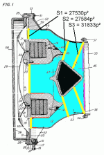
Hello WHG,
Thanks for the "good morning" even if here in Paris it is evening and I am about to get back home for dinner...(18H37mn).
You are right, in the Thuras bass driver the smallest front wave area in the ducts from the diaphragm to the throat of the horn is seen near the diaphragm.
See attached graph with 3 areas calculated.
That's why I did the remark about the 2 different aspect to consider: the low-pass filter behaviour of the compression cavity and what geometry to consider to calculate the efficiency...
Specially in the case of the Thuras bass compression driver, we cannot use a simple common geometry in order to study the 2 aspects.
Due to their shape I guess we may ignore the standing waves in the cavities.
Have a good week-end!
Best regards from Paris, France
Jean-Michel Le Cléac'h
Good Morning JMMLC,
Within the granularity of the unit of measure, a pixel, either formula is sufficiently accurate.
We are all supposed to be having fun here.
Note that the area of front-center chamber of the Thuras driver is smallest nearest the diaphragm, not at the annular exit. In any event both front cavities should be modeled separately and then their outputs combined. If output upper frequency limit is kept low so that wavelengths are much larger than cavity dimensions, then standing wave modes in these cavities, both front and back, may be ignored. Only the avoidance of air-flow turbulence need be addressed in an enhanced design.
Regards
WHG
Attachments
- Status
- Not open for further replies.
- Home
- Loudspeakers
- Multi-Way
- DIY bass compression drivers
