That's pretty distressing. None of the replacements are really on a par. Many tradeoffs for lower noise and wider bandwidth. The HF noise corner is much lower on all the others as well.
If you run AK5578 in mono mode, ie; 8 -> 1, it should be capable of good enough performance, looking at measurements of RME ADI-2 Pro.
Obviously using sample rates above 192k brings more HF noise. Yes HF noise corner is lower but you can get 130dB DR (20k BW) so you win some / loose some.
Otherwise, I guess you better start cooking up a 24 or 32 bit SAR ADC.
T
It's kind of a pain to use the AK5578 in mono mode, you'll have to have an input buffer than can actually drive 8 differential ADC inputs without distorting or have the added cost and real-estate of 8 channels worth of input buffers.
It's kind of a pain to use the AK5578 in mono mode, you'll have to have an input buffer than can actually drive 8 differential ADC inputs without distorting or have the added cost and real-estate of 8 channels worth of input buffers.
Stop being a pussy! 😀 😀
Driving 4 or 8 channels of 3.6k IP Z is not too hard, especially at the small voltage swings required. The bottom line is, it may be the only decent option after the 5394's run out.
T
🙂
Yeah I suppose it's not that bad, might be good with a composite amplifier.
Aside from the SAR ADC Frex is using, this is something that caught my eye:
http://www.ti.com/lit/ds/symlink/ads127l01.pdf
Now, I haven't gone through the datasheet thoroughly to see what tradeoffs there are in the various modes it has. Nice looking part though.
It would seem that this application is intended for this chip.
-Chris
(from the data sheet)2 Applications
• Vibration and Modal Analysis
• Data Acquisition Systems
• Acoustics and Dynamic Strain Gauges
• Power Quality Analysis
-Chris
Hmm.. typically all items in the list are low frequency, high precision applications. Is it high speed enough for audio?
8 channels of AK5578 summed - yummy! But whoever starts such a project also needs to use the same 'fix' that RME added to their ADI-2 Pro to reduce the chip's frequency response ripple, which otherwise makes the AK a bad choice for measurements.
ADI-2 Pro Firmware Update DSP 21 (details) (Page 1) — ADI-2 Pro & ADI-2 DAC — RME User Forum
ADI-2 Pro Firmware Update DSP 21 (details) (Page 1) — ADI-2 Pro & ADI-2 DAC — RME User Forum
Surprised they went so cheap on the filter. The AK5397 seems to be better in this regard but it seems to have worse distortion performance. Annoying that they are discontinuing their only ADC with no compromises.
This chip has a lot of uC connections. Can it also operate stand-alone?
Probably not. None of the customers for these parts would want to use it in hardware mode.
This chip has a lot of uC connections. Can it also operate stand-alone?
Which chip are you referring to?
The AK5397 only has a hardware control mode, no SW control. You can of course use a uC to set the control pins, but it also works fine with a pure hardware pin control. That was what I used in the initial design, when I used the AK5397, before I discovered the relatively poor distortion performance.
If only the distortion could be improved! In terms of noise it is a very good part.
It certainly looks promising.
Just stumbled on this part, haven't looked in depth but it might be worth a look also:
https://www.analog.com/media/en/technical-documentation/data-sheets/AD7768.pdf
It looks like a clone of the TI part (or vice versa). Maybe some patents expired.
Linearity/distortion is good. Noise not so much. I like the small footprint. The noise floor is flat to 100 KHz (like the AK5394A). The output format is not I2S but can be converted. With 8 converters is should be possible to add them with DSP to get better SNR (almost 9 dB??) and maybe some distortion reduction if they are put together optimally.
Linearity/distortion is good. Noise not so much. I like the small footprint. The noise floor is flat to 100 KHz (like the AK5394A). The output format is not I2S but can be converted. With 8 converters is should be possible to add them with DSP to get better SNR (almost 9 dB??) and maybe some distortion reduction if they are put together optimally.
It looks like a clone of the TI part (or vice versa). Maybe some patents expired.
Linearity/distortion is good. Noise not so much. I like the small footprint. The noise floor is flat to 100 KHz (like the AK5394A). The output format is not I2S but can be converted. With 8 converters is should be possible to add them with DSP to get better SNR (almost 9 dB??) and maybe some distortion reduction if they are put together optimally.
Yeah, it would take parallel converters to match the AK5394A in the audio band probably. The LT SAR part is probably still better overall, especially considering it gives you opportunities to look higher.
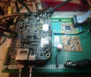
I'm just playing with the LT2500-32, connected to a Beagle Bone Black.
Had lots of problems to make the BBB work with the SPI interface; The CPLD
that creates the sampling clock from 100 MHz then had just enough resources
to make a 32 bit USART + mux , so I now read 4 bytes via the parallel register
interface. The SPI of the BBB would not have supported the full 1 MSPS anyway.
The register interface is taken care of by one of the 2 PRUs, extraneous 32 bit RISCs
with predictable latency and 5 nsec per instruction. They talk to the 1 GHz ARM
processor via shared ram. The ARM runs Debian linux, one can ssh into it and
compile all the programs locally on the ARM with the standard Linux tools.
The interface to the rest of the world is the LAN.
My PC can simply open port 5025 on 192.168.178.111 and write/read GPIB/
IEEE488/SCPI style commands / data. The BBB should be fast enough to run
FFTW locally; I could compile it already. Not bad for a $55 computer.
The LT2500-32 is the small rectangle on the stamp-sized circuit board in the
foreground. There are also 2 LT3042 as local positive regulators, a -3V regulator,
full differential ADC driver (LT6263???) and a LT6655 as reference. The CPLD is a
$2 Xilinx Coolrunner.
Still quite a long way to go, I'm just getting first samples and can setup the ADC.
regards,
Gerhard
Attachments
Last edited:
Returning to my line-hum-with-unbalanced-cabling issue 🙂
To recall the problem arises when the cabling is: BNC-out, BNC cable, BNC-to-XLR-adapter at the input.
I have meanwhile added an battery power option with a switch, so that I can switch between line and battery power without the need touch anything in the measuring setup.
Some loopback measurements:
First, the ilustration of the problem, the line powered measurement (red) over the same measurement with battery power (green). Battery powered the line artefacts are gone.
.jpg")
Next the same measurement, both cases battery powered. First (red) the line power connected to the analyser and the transformer is line powered, but not connected to the analyser PCB. Second (green) line power unplugged.
You see, there is no difference. An indication that the transformer stray might not be the problem ... but keep in mind the transformer is driving no load here.
.jpg")
Last I compare line powered balanced (red) to battery powered unbalanced (green) measurement. (I did not alter the generator settings for that the harmonics do not change. Therefore the signal is 6dB stronger in balanced setup.)
 Pegerl gen unverändert (also bal 6dB höher).jpg")
Conclusion: it is possible to get the same performance unbalanced as ballanced, with the not recommended unbalanced cabling topology, at least if you power the analyser from batteries.
To recall the problem arises when the cabling is: BNC-out, BNC cable, BNC-to-XLR-adapter at the input.
I have meanwhile added an battery power option with a switch, so that I can switch between line and battery power without the need touch anything in the measuring setup.
Some loopback measurements:
First, the ilustration of the problem, the line powered measurement (red) over the same measurement with battery power (green). Battery powered the line artefacts are gone.
Next the same measurement, both cases battery powered. First (red) the line power connected to the analyser and the transformer is line powered, but not connected to the analyser PCB. Second (green) line power unplugged.
You see, there is no difference. An indication that the transformer stray might not be the problem ... but keep in mind the transformer is driving no load here.
Last I compare line powered balanced (red) to battery powered unbalanced (green) measurement. (I did not alter the generator settings for that the harmonics do not change. Therefore the signal is 6dB stronger in balanced setup.)
Conclusion: it is possible to get the same performance unbalanced as ballanced, with the not recommended unbalanced cabling topology, at least if you power the analyser from batteries.
- Home
- Design & Build
- Equipment & Tools
- DIY Audio Analyzer with AK5397/AK5394A and AK4490