I agree that the noise looks suspiciously low. It is difficult to read the exact value, but in the flat region it could be something like -177dBV/sqrt(Hz). This is equivalent to 1.41 nV/rtHz. The input noise is low, but not quite that low. I would expect something like 4 nV/rtHz.
@PaulBC
Can you provide some details of the test setup, like cable connections, terminations etc.?
@PaulBC
Can you provide some details of the test setup, like cable connections, terminations etc.?
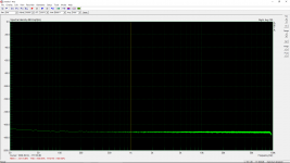
@JensH, you are right. It was just a simple stupid mistake. I thought the unit of the input gain setting in ARTA is dB, therefore I set it as "20". However, it is a 20X gain, not a 20dB gain (i.e., 10X gain). That is why the noise floor is only half of the expected value. My apologies.
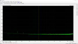
The key I posted this screenshot is to show there is no 60Hz harmonics under the -20dBV input configuration if the transformer is moved away, not the noise level. It is just a shorted-input measurement. However, even a shorted-input measurement, these 60Hz harmonics are also there under the -10dBV and -20dBV input configurations with the internal transformer. Therefore, moving the transformer away benefits not only single-ended but also low-level balanced measurements.
I attached three screenshots:
1. noise floor with a correct gain setting (-20dBV, shorted input).
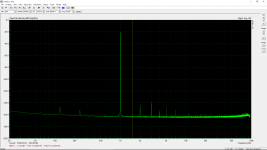
2. single-ended measurement with 0dBV input and output.
3. single-ended measurement with -20dBV input and output.
For 2 and 3, I used zfe's configuration and the results are consistent with zfe's results except the odd harmonics of 60Hz. It shows that moving the transformer much further away just reduces the odd harmonics of 60Hz with a single-ended measurement. To suppress the even harmonics of 60Hz, some additional efforts have to be made (e.g., battery or SMPS).
The key I posted this screenshot is to show there is no 60Hz harmonics under the -20dBV input configuration if the transformer is moved away, not the noise level. It is just a shorted-input measurement. However, even a shorted-input measurement, these 60Hz harmonics are also there under the -10dBV and -20dBV input configurations with the internal transformer. Therefore, moving the transformer away benefits not only single-ended but also low-level balanced measurements.
I attached three screenshots:
1. noise floor with a correct gain setting (-20dBV, shorted input).
2. single-ended measurement with 0dBV input and output.
3. single-ended measurement with -20dBV input and output.
For 2 and 3, I used zfe's configuration and the results are consistent with zfe's results except the odd harmonics of 60Hz. It shows that moving the transformer much further away just reduces the odd harmonics of 60Hz with a single-ended measurement. To suppress the even harmonics of 60Hz, some additional efforts have to be made (e.g., battery or SMPS).
Attachments

I would qualify a shorted input as balanced measurement.
For the unbalanced noise floor I would go for the setup of a unbalanced loop back measurement with no signal playing.
For the unbalanced noise floor I would go for the setup of a unbalanced loop back measurement with no signal playing.

There is also a lot of pickup of environmental noise possible.
Here two unbalanced loop-back noise floor measurements, -20dbV in, on battery power (!), no line connected, in a noisier environment.
The setup is: out to 1.5m RG58 BNC cable to BNC-XLR adapter at input.
First the BNC cable is routed as a big loop

Second the BNC cabel is routed such that it encloses only minimal surface.

Here two unbalanced loop-back noise floor measurements, -20dbV in, on battery power (!), no line connected, in a noisier environment.
The setup is: out to 1.5m RG58 BNC cable to BNC-XLR adapter at input.
First the BNC cable is routed as a big loop
Second the BNC cabel is routed such that it encloses only minimal surface.
Analog Precisions PSU is completely shielded (toroidal transformer inside). Moreover a full metal case is needed (no plastic, no aluminium).
Analog Precisions PSU is completely shielded (toroidal transformer inside). Moreover a full metal case is needed (no plastic, no aluminium).
Do you mean ferrous or high permeability metal? Aluminum is a metal last I checked 😉.
I wonder how much better the R-core transformer from the original plans would be.
I haven't found any evidence that the stray field of an R-core would be better than a toroid. They should be worse than a toroid in that respect ideally. The R-core might be better in terms of interwinding capacitance, but overall could be even worse for this application.
Guys can I ask a dumb question: so far I have been using the RTX on and off with my dscope software. I found though that I can’t get the right voltage out - when I set the dscope to generate 500mV rms on RTX I am getting about 690mV instead when I measure this voltage using a scope or a dscope hardware. When I measure the same voltage using the RTX, it reads 500mv. This is weird ...
Any ideas why and how I can fix this ?
Any ideas why and how I can fix this ?
I don't know the dscope, so the following is a guess.
Could it be that the scaling between mV and dBFS is different on the dscope compared to the RTX6001? If the "about 690 mV" is actually 707 mV it could be a difference of 3dB.
On RTX6001 the 1V/0dBV output setting will get you a 500 mV output (balanced) with a sine wave at -6dBFS (6dB below the clipping level).
Also the 0.707 is the peak level of the 0.5 RMS ...
Jan
This is true if the signal is a sine. But sines can be boring after a while, so some people use different signals sometimes ;-) Non-sine signals will have different conversion factors between peak and RMS!
Any ideas why and how I can fix this ?
Is your test signal a sine?
The voltage values printed on the RTX front panel are RMS values assuming sine signals, but they are just plain wrong if some other test signal shape is used. Since I am one of those people who think that sines get boring after a while, I kept falling in this trap all the time when I tried converting from "digital full scale" to actual voltages. To stop me from screwing up all the time I just converted the front-panel numbers to peak values (using the underlying 0.707 factor) and put new labels on the RTX front giving those peak values. These are independent of the signal form, and are therefore more meaningful for the conversion from "digital full scale" to actual voltages.
yes the test signal is a simple 1khz sine.
I will try to check the dbfs scaling as the possibility. I think that several others here are also using the dscope software (it really rocks!) with the RTX so any expereinces there would also be helpful.
I will try to check the dbfs scaling as the possibility. I think that several others here are also using the dscope software (it really rocks!) with the RTX so any expereinces there would also be helpful.
Is there anyone successfully using RTX6001 as default input device under Windows 10? It turns out I could not record anything through Audacity or Windows build-in voice recorder. So far my RTX6001 will only work as an input device under REW through ASIO. If I apply "Java" on drivers setting, the input will not work anymore. BTW, I am using the driver and firmware that came with RTX6001.
Poting
Poting
I just tried recording using Reaper and ASIO on Win 10. Worked fine. I'll try using the Thesycon Windows driver but in some earlier testing it seemed fine. The Win audio engine can be a PITA to setup for nonstandard devices like this. You would look for the RTX and you may need to reinstall since Windows likes to think it has a native driver. You must replace that with the RTX driver. The native driver doesn't understand record.
The native driver has no problem to record. canvas might need to allow the 'microphone' (totally stupid new security setting in Win 10) to see input signals.
- Home
- Design & Build
- Equipment & Tools
- DIY Audio Analyzer with AK5397/AK5394A and AK4490