The RTX6001 output levels are indicated in Vrms, so if you output a full scale signal and set the output attenuator to the 1 V range, you will get 1 Vrms balanced (across plus and minus wires).
The single ended output, either from the BNC or from the plus output of the XLR relative to pin 1, will be 0.5 Vrms in that case.
I agree that on the output side, the BNC should be used for amplifiers with a single ended input. The ground loop through the safety earth can be a problem though.
The single ended output, either from the BNC or from the plus output of the XLR relative to pin 1, will be 0.5 Vrms in that case.
I agree that on the output side, the BNC should be used for amplifiers with a single ended input. The ground loop through the safety earth can be a problem though.
I agree with what you wrote, in principle. But it's not relevant to my question, because I do not use dB or some other form of normalisation to some reference level. I just used the absolute voltages as they came out of the RTX. Please take a look at the y-axis label of my figure.If you are telling you analyzer to output 1 volt in balanced mode that is 1 volt P to P across the minus and plus pins, that shows up on the FFT plot as 0dBV.
If you are telling you analyzer to output 1 volt in balanced mode and you connect it Plus pin to shield that is only 0.5 volt P to P. On the FFT plot that shows up as -6dBV. (negative is floating)
You have lost 6dBV, you may think that is a improvement on the noise floor.
Using the balanced connection and a RCA adaption you can connect it the way you did the 6dbV will not be lost. Do it as Audio1 suggests the negative output is floating. it may work out well testing and noise wise. the connection is single end with a apparent balanced XLR output. However 0.5 volts or 6dBV is MIA.
It is easy to make a cognitive error.
Why not follow the AP recommendation of using the single end BNC output and cable?
DT
Also, I have tried the BNC out. Didn't make a difference. I have stated this repeatedly in my previous posts.
I agree that on the output side, the BNC should be used for amplifiers with a single ended input. The ground loop through the safety earth can be a problem though.
Jens, what are the options to deal with the ground loop?
The classic solution going back to the ST1700 is to connect the BNC to the dut input and use the xlr differential with no ground for the DUT output. There is a ground loop passing current through the BNC shield. in the ST1700 it seems the chassis is not connected to signal ground, just safety ground. Some products have a series resistor between the two grounds of 10 or 50 Ohms. Safety regulations have a strong impact on this.
I have repeatedly noticed (very) slight "inconsistencies" regarding the noise level and the line artefacts measuring a single-ended-out with the differential approach (the "no 17" connection).
I used a pin 1-3 shorted connection on the other channel, on which the measurements did not change noticeable but has more line artefacts, to compare. The noise floor of the differential connection rises or falls sometimes when I physically do not change anything, or it falls (or rises) when I use the separate ground connector of the RTX 6001 to connect with the DUT (OK) but then stays there when I remove the separate ground connection again.
Analogue things happen for the line artefacts. Moreover this happens somehow randomly with longer "stable" phases in-between.
Of cause the level where these effects happen is very low (e.g. for the noise floor about -150dBFS and the variations are about +-5dB). But it is somehow annoying nevertheless if you try to get rid of line artefacts or to lower the noise floor in that area, as you never know if its real or spook.
As I think to have noticed such also with loopback measurements I hesitate to blame entirely the DUT or the connection. Does the AK5394 ADC perhaps do from time to time sometimes something like an internal calibration which might be the reason?
As far as I know, the ADC does not do calibration during operation, only at startup.
Do you have measurements showing the noise and perhaps the variation?
Is it line related, and if so, at what frequency do you see the variation?
Or is it wideband noise?
Do you have measurements showing the noise and perhaps the variation?
Is it line related, and if so, at what frequency do you see the variation?
Or is it wideband noise?
As far as I noticed, only the line artefacts and the wide band noise are affected. The signal and harmonics seem to be stable and consistent.
I will try to capture some measurements. As it happens somehow unexpected I have not yet captures of good examples where I can give all details of the setting.
I will try to capture some measurements. As it happens somehow unexpected I have not yet captures of good examples where I can give all details of the setting.
I have repeatedly noticed (very) slight "inconsistencies" regarding the noise level and the line artefacts measuring a single-ended-out with the differential approach (the "no 17" connection).
The noise floor of the differential connection rises or falls sometimes when I physically do not change anything, or it falls (or rises) when I use the separate ground connector of the RTX 6001 to connect with the DUT (OK) but then stays there when I remove the separate ground connection again.
Analogue things happen for the line artefacts. Moreover this happens somehow randomly with longer "stable" phases in-between.
Hi
I noticed this type of noise floor jumping only with Flaky connections - whenever I tried to measure source like HP 239A. If you can connect without any breakage of earth - it does not happen. Now I have made a specific socket to connect single ended input in to RTX - using balanced connector to RTX ( as recommended by Jen). RTX definitely needs a single ended input ( even if the noise specification is inferior, to avoid cable issues. I have an AP Sys 2 and find such an input a great help while testing. However I am not happy with FFT and so RTX need. I am still thinking of using Single ended to Balanced electronic converter and see how it works as we can then use balanced connector from Single ended source. Since I am not measuring sources that are not that low noise and primary purpose is to evaluate THD, it might work.
Hey Jens. First of all. It is a pleasure to work with the RTX!
I am working on software to control the attenuator settings. Already found the HID protocol description. I am curious about the "overflow" and "high voltage" bits. How do they distinguish?
As far I understand:
# "overflow" occurs every time we hit the end of one range i.e. 1V 3.16V, 10V etc.
# high voltage occurs if more than 100V are present at the input? What is this indication good for? There is no possibility to physically disconnect the input signal from the analyzer (I have used a series relais for similar protections)??
Currently I am thinking of setting the ADC target input level to 50%FS with a allowed window of 25% and a little hysteresis. Means, the attenuator should find a range where the input is between 25%FS and 75%FS. Any further thoughts on this from the designer of the instrument? 🙂
Concerning the groundloop Issues...
I have some studio-grade small signal audio transformers (Pikatron i think). Maybe a easy solution? I will verify the performance of these soon.
I have some studio-grade small signal audio transformers (Pikatron i think). Maybe a easy solution? I will verify the performance of these soon.
I have thought along these lines too, but I don't want to insert anything to the signal path that might mess up the signal.Concerning the groundloop Issues...
I have some studio-grade small signal audio transformers (Pikatron i think). Maybe a easy solution? I will verify the performance of these soon.
What about an isolation transformer in the mains line? Anything wrong with that?
I have thought along these lines too, but I don't want to insert anything to the signal path that might mess up the signal.
What about an isolation transformer in the mains line? Anything wrong with that?
you could just use a cheater plug
It depends 😉What about an isolation transformer in the mains line? Anything wrong with that?
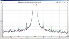
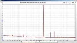
Did some loopback test in various 230V configurations to get rid off the mains peaks:
Too small audiophile transformer (Stein T1 MKII; some 30-50 VA, I guess) brings side line at mains frequency (50Hz) appart from the carrier:
A 500VA Topaz noise isolation transformer performs much better in that aspect.
Reduction of mains peaks was surprisingly low:
Attachments

Hi nyt,
Never disconnect the safety ground from anything!
-Chris
How about ... NO!!!you could just use a cheater plug
Never disconnect the safety ground from anything!
-Chris
Hi nyt,
How about ... NO!!!
Never disconnect the safety ground from anything!
-Chris
yeah, obvious disclaimer, but you could just use a cheater plug, especially if you're testing something on a bench.
It depends 😉
Did some loopback test in various 230V configurations to get rid off the mains peaks:
Too small audiophile transformer (Stein T1 MKII; some 30-50 VA, I guess) brings side line at mains frequency (50Hz) appart from the carrier:

A 500VA Topaz noise isolation transformer performs much better in that aspect.

Reduction of mains peaks was surprisingly low:

Why would an isolation transformer be useful in a loopback test? There is no ground loop, because there is no DUT with a safety earth connection involved in loopback test.
Can you try your isolation transformer(s) with a DUT that connects its GND to safety earth?
A cheater plug is never a good idea, and advocating for its use is also a violation of forum policy. Don't make me put my mod hat on ok? 😀
Lundahl and others make very good 1:1 transformers which can be applied to this problem on either source or measure side. I used Western Electric REP 111C coils for this purpose in the past and despite the mediocre specifications found that they minimally degraded performance out to about 30kHz and did not add much distortion at the levels I used them at. (I achieved an sfdr of better than 110dB with them in at <1Vrms) I will be retrofitting my pair with XLR connectors for use with the RTX on the rare occasion that they are needed. Best performance is usually achieved when driven by a low source impedance.
Lundahl and others make very good 1:1 transformers which can be applied to this problem on either source or measure side. I used Western Electric REP 111C coils for this purpose in the past and despite the mediocre specifications found that they minimally degraded performance out to about 30kHz and did not add much distortion at the levels I used them at. (I achieved an sfdr of better than 110dB with them in at <1Vrms) I will be retrofitting my pair with XLR connectors for use with the RTX on the rare occasion that they are needed. Best performance is usually achieved when driven by a low source impedance.
A cheater plug is never a good idea
Does that apply to an isolation transformer, too?
Hi mbrennwa,
I use isolation transformers for the D.U.T. all the time. The safety ground is continued through the isolation transformer from input to output directly. There isn't anything that legally allows you to interrupt the safety ground connection if the equipment was designed with one. Obviously using a double insulated device avoids this issue to begin with.
-Chris
- Home
- Design & Build
- Equipment & Tools
- DIY Audio Analyzer with AK5397/AK5394A and AK4490