I never meant to suggest a GFCI is better than grounding. They both are very valid. GFCI's can fail since they are active circuits. Ground wires are less likely to fail but they also do for various reasons like corrosion, neglect, installation error.
In my house most power outlets don't even have a ground connection. They are only available in the "wet rooms" like kitchen, bathroom and utility room.
But there is a ground fault interrupter at a central place, where power is coming into the house. It is a 40A relay that will switch off if a leakage current above 30 mA is detected. This has been required by law since 1975.
In the room where I normally work with the analyzer (when at home), I don't even have a power outlet with a ground connection.
So most of the testing has been done without the ground wire connected. At RTX this is different. There we use plugs with ground as a standard.
Ground faults on 20A circuits were taking out entire systems because the main breaker upstream had code-required GF protection, and the little 20A branch breaker did not. So with a ground fault, the main breaker's GF protection was faster than the 20A overcurrent device, and the main breaker tripped. They add a second level of GF protection simply to coordinate with upstream protection.
Secondary GF protection in any form has nothing to do with protecting the upstream transformer. It is there to reduce fires on the equipment that has faulted, as ground faults are normally arcing faults. Transformers could care less if they have a secondary ground fault, to the transformer it's no different from other types of through faults. We won't get into the 58% issue.
GFCI is all about personnel safety, in the mA range. System GF protection is about fire avoidance, in the 1A - 1200A range. The fire risk is at the faulted equipment, not the transformer.
Long time PE in 5 states, including California.
We are getting closer.
Yes without fault protection we are talking about arcing faults. Assume a fault occurs in the 20 amp circuit. Once the arc is initiated inside the panel the arc blast is current limited only by the upstream conductors and devices.
The tap rules are all about protecting upstream conductors and transformers.
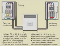
The attached graphic is from the link.
Feeder and Transformer Secondary Tap Conductors | IAEI Magazine
DT
Attachments
Would that be why Mr. Tesla immersed his ground structures in concrete under
his orbs?
The proposed method of wireless transmission of electricity, is that compatible
with aircraft, birds, drones? automobiles? High rise buildings?
his orbs?
The proposed method of wireless transmission of electricity, is that compatible
with aircraft, birds, drones? automobiles? High rise buildings?
We are getting closer
DT
I'm not sure we are. This last post has nothing to do with ground fault protection. Introducing the 'tap rule' is also not relevant to the discussion thus far. Tap rule has nothing to do with arc flash and nothing to do with protecting the upstream transformer.
Arc flash has nothing to do with ground fault, so much so IEEE rejects the use of ground fault characteristics to calculate arc flash incident energy. I think you are getting confused on your terminology.
Hey Jens. First of all. It is a pleasure to work with the RTX!
I am working on software to control the attenuator settings. Already found the HID protocol description. I am curious about the "overflow" and "high voltage" bits. How do they distinguish?
As far I understand:
# "overflow" occurs every time we hit the end of one range i.e. 1V 3.16V, 10V etc.
# high voltage occurs if more than 100V are present at the input? What is this indication good for? There is no possibility to physically disconnect the input signal from the analyzer (I have used a series relais for similar protections)??
Currently I am thinking of setting the ADC target input level to 50%FS with a allowed window of 25% and a little hysteresis. Means, the attenuator should find a range where the input is between 25%FS and 75%FS. Any further thoughts on this from the designer of the instrument? 🙂
@Jens: I think my prev. post got lost in the "noisefloor" 😉
Here some pictures of measurements, with different cables, of the Victor generator, powered by an (two pin) plug in power supply - thus floating. This power supply is an older one with transformer and linear regulators.
The RTX6001 was set to 10dBV. AudioTester was set to van Hann window, FFT length 2^19, averaging 3. No averaging did not look much different.
First picture; differential connection (as the suggested no 17 of...) with a separate connection RTX ground connector, Victor ground connector.

Second picture; The same as above, without the ground connection 😉

Third picture; Using a commercial XLR-BNC connector (XLR Pin 1 and 3 shorted), with the additional ground connection.

Fourth picture: The same as above without the additional ground connection - and no, I did not mixed up the pictures.

Fifth picture: A differential connection were pin 2,3 are connected with an 1k resistor to pin 1, as suggested by Demian here post5270704 (without the additional ground connection - as this would not make much sense, I think). The output power is slightly reduced due to the resistors.

The RTX6001 was set to 10dBV. AudioTester was set to van Hann window, FFT length 2^19, averaging 3. No averaging did not look much different.
First picture; differential connection (as the suggested no 17 of...) with a separate connection RTX ground connector, Victor ground connector.
Second picture; The same as above, without the ground connection 😉
Third picture; Using a commercial XLR-BNC connector (XLR Pin 1 and 3 shorted), with the additional ground connection.
Fourth picture: The same as above without the additional ground connection - and no, I did not mixed up the pictures.
Fifth picture: A differential connection were pin 2,3 are connected with an 1k resistor to pin 1, as suggested by Demian here post5270704 (without the additional ground connection - as this would not make much sense, I think). The output power is slightly reduced due to the resistors.
Here some pictures of measurements, with different cables, of the Victor generator, powered by an (two pin) plug in power supply - thus floating. This power supply is an older one with transformer and linear regulators.
The RTX6001 was set to 10dBV. AudioTester was set to van Hann window, FFT length 2^19, averaging 3. No averaging did not look much different.
First picture; differential connection (as the suggested no 17 of...) with a separate connection RTX ground connector, Victor ground connector.
View attachment 660052
Second picture; The same as above, without the ground connection 😉
View attachment 660053
Third picture; Using a commercial XLR-BNC connector (XLR Pin 1 and 3 shorted), with the additional ground connection.
View attachment 660054
Fourth picture: The same as above without the additional ground connection - and no, I did not mixed up the pictures.
View attachment 660055
Fifth picture: A differential connection were pin 2,3 are connected with an 1k resistor to pin 1, as suggested by Demian here post5270704 (without the additional ground connection - as this would not make much sense, I think). The output power is slightly reduced due to the resistors.
View attachment 660056
Thanks for this! Number 1 and 4 are very clean overall, don't show any mains hum. Lesson learned: use exactly one GND connection, avoid ground loops 🙂
Avoiding ground loops is usually not too difficult if there is only one safety earth connection (usually the one at the RTX). I am currently messing around with situations where the DUT also has a safety earth connection, so there are two GND connections between the DUT and the RTX. It seems to me like it's sometimes easier to live with the ground loop than trying to beak it, and adding a third GND connection in the form of a thick, short wire between the DUT and RTX chassis sometimes actually reduces the hum+noise. Maybe I'll post a few measurements later.
@Jens: I think my prev. post got lost in the "noisefloor" 😉
Almost, but not quite 🙂
"Overflow" is detected by the XMOS processor, based on the audio signal coming from the ADC. When the peak level is close to full scale it will detect it as overflow.
The "high voltage" indication is a hardware signal inside the analyzer. This signal can be monitored via the HID protocol. The signal is part of the protection against "high" voltages that could potentially destroy the analyzer. When setting the input attenuator to the sensitive settings 10 dBV, 0 dBV, -10 dBV and -20 dBV there will be an almost direct connection between the input terminals and the input amplifier. When the "high voltage" signal becomes active it will physically disconnect the amplifier from the input using a relay.
The optimum input level depends to some degree on what you are trying to measure. The distortion of the ADC does increase when approaching full scale, so if you want to have a minimum distortion it is normally better to stay below e.g. -10 dBFS. The 20% to 75% is probably a good starting point.
@zfe
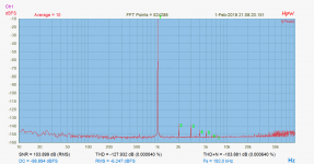
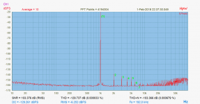
The distortion numbers look strange. In the first measurement the distortion is shown as -78.5. The signal is at -6.88 dBFS, the second harmonic is around -150 dBFS, the 5th harmonic is slightly lower and the noise floor is close to -160 dBFS. So where did the -78.5 dB come from? Is there a problem with the window type or other settings?
The distortion numbers look strange. In the first measurement the distortion is shown as -78.5. The signal is at -6.88 dBFS, the second harmonic is around -150 dBFS, the 5th harmonic is slightly lower and the noise floor is close to -160 dBFS. So where did the -78.5 dB come from? Is there a problem with the window type or other settings?
For the moment I was only interested in the diagram.
As the distortion number is almost the same as the S/N almost all should come from noise.
With that FFT size we have 2^18 bins we have a total noise of about 54dB above the displayed floor, the signal is about -7dB. So over the thumb that would be about 90dB S/N. That is still better than the displayed value but not "enormously".
I check tomorrow the settings and see if I get reasonable values.
Do you get similar results with another amplifier?
What if the other amplifier is not directly connected to the mains Protective Earth? i.e. use a Disconnecting Network between Main Audio Ground and protected Chassis
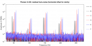
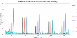
I made a few more measurements with two other amplifiers. One was a FirstWatt F5 (built on NP's kitchen table) and a Pioneer A-445 integrated. The F5 has a three-prong mains connector, the Pioneer a two-prong. The F5 has a ground loop breaker between the audio GND and chassis (12 Ohm or so).
The software was set to output "silence" at the RTX. The RTX output range was set to 1V, the input range was set to 10V.
All measurements were made with an 8 Ohm speaker dummy load, with the RTX input connected across this dummy (XLR pins 2 and 3, pin 1 not connected).
The amplifer RCA inputs were connected in different ways:
A: amplifier input shortened (not connected to RTX)
B: like A, but with an additional thick, short wire between the RTX and amplifier chassis
C: RTX BNC to amplifier RCA input at amplifier
D: like C, but with additional wire between RTX and amplifier chassis
E: RTX XLR-to-RCA adapter to RCA input at amplifier
F: like E, but with additional wire between RTX and amplifier chassis
G: RTX balanced to RCA input at amplifier (Rane No 6, or No 13 backwards)
H: like G, but with additional wire between RTX and amplifier chassis
The idea of the additional wire connecting the RTX and amp chassis was to provide a solid GND reference for the Pioneer amp (two prong) for the Rane No 6 setups. However, the G and H setups resulted in oscillations with the Pioneer amp, so I only measured the F5 in these setups.
In general, the BNC connection without the additional connection between the chassis (setup C) gave the best results after the shortened amp input (A or B).
Questions:
- These somewhat more systematic measurements show that the BNC connection (C) tends to give less noise than the XLR-to-BNC adapter (E). I thought the XLR-to-RCA adapter gives the same connections as the BNC out. Why are the results different (both with F5 and Pioneer)?
- Setup G avoids the ground loop with the F5 amp, so I expected this would give the lowest noise. The measurements show the opposite. Why?
- In setup H, the additional wire between the RTX and amp chassis basically defeats the ground loop breaker in the amp. Why does that give lower noise?
Attachments
Last edited:
@zfe
The distortion numbers look strange. In the first measurement the distortion is shown as -78.5. The signal is at -6.88 dBFS, the second harmonic is around -150 dBFS, the 5th harmonic is slightly lower and the noise floor is close to -160 dBFS. So where did the -78.5 dB come from? Is there a problem with the window type or other settings?
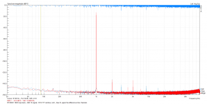
Here is the same measurement with Arta, which reports about 105dB THD+N.

Playing around with AudioTester I think the reason for the lower value is that the fundamental of the victor generator is quite wide and at some point the "fundamental" is counted as noise. Arta seems to have a different threshold. One indicator, with AudioTester, is that if I limit the bandwidth, taken into account for the distortion, is reduced to +- a few Hz around 1000Hz I get still a value around 70dB.
Is there some norm or setting where the fundamental ends an noise begins?
Here you deal with the various SW tools behavior or possible configurable settings of those. 😀
On LDO, you get a wide noise bell and would like to skip/get ride of the THD & SNR calculation. With the danger to ignore/skip any spurious/artifacts closed to the fundamental for the SFDR calculation.
I could happy setup such required setup using my licensed HpW Works SW.😎
BB
On LDO, you get a wide noise bell and would like to skip/get ride of the THD & SNR calculation. With the danger to ignore/skip any spurious/artifacts closed to the fundamental for the SFDR calculation.
I could happy setup such required setup using my licensed HpW Works SW.😎
BB
Here it is a quick comparison of the RTX in loop vs. a modified, updated Mirand V 1.1 dac from Sonny Andersen (sonnya)
The dacs are always set at -10dBFS. The slight amplitude difference is because of the different output gain factor (higher for the Mirand, than that of the 0dBV setting in the RTX)
First is the RTX in loopback, 0dBV out-in. Second is the Mirand at the same resolution. Last is the Mirand at a better software resolution.
Attachments

I normally just set the inputs and outputs to 32 bit and leave the rest as default. Whether you set the input to 24 or 32 bit makes no difference by the way because the ADC is a 24 bit device. Avoid 16 bit if you can.
Latency (buffer size) is normally not an issue when doing test, so no reason to reduce buffer size etc. with the risk of getting errors because the PC is too slow to service the audio transfer.
If you use the ASIO for live music applications, this could be different, because in that situation you probably would want to minimize the latency.
Here a loop-back 192K test in ARTA with 131K FFT window.
Red is left channel, Blue is right channel, the upper is the difference btw thw two channels.
The THD result is lower than Joseph K., perhaps due to different FFT Spectrum Software or FFT wnd (131K vs 530K).
Better results, I have with the 44K capture.
JensH, you have made a marvelous job with the RTX, my congrats.
Attachments
- Home
- Design & Build
- Equipment & Tools
- DIY Audio Analyzer with AK5397/AK5394A and AK4490