Here is a plot showing the IM performance of the RTX. I'm using my set of Victor oscillators. They are all separately battery powered. This is 11.2 KHz + 12 KHz. First is an EMU 1212M with opamp upgrades, second is the RTX. Both use the same ADC. Clearly the analog circuitry on the EMU is not giving the AK5394A its best. The RTX performance is exceptional.
Attachments
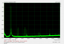
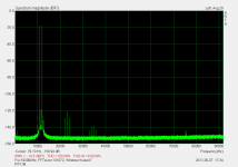
Here is a plot showing the IM performance of the RTX. I'm using my set of Victor oscillators. They are all separately battery powered. This is 11.2 KHz + 12 KHz. First is an EMU 1212M with opamp upgrades, second is the RTX. Both use the same ADC. Clearly the analog circuitry on the EMU is not giving the AK5394A its best. The RTX performance is exceptional.
I am wondering whether USB cable differences will show up or not in these measurements.
In my experience with USB audio sound cards, generally 30cm USB cable length will give the most balanced sound. Longer cabling with give more bass but the sound is not as clear; shorter cables will give less bass and more fatiguing sound. If this can show up in measurements, it would certainly be helpful.
I have tried the Xonar U7 and the Meridian explorer. These are USB powered devices. Both end up with the same cable length.
Sent from my iPhone using Tapatalk
Last edited:
I did a bunch of tests with cables from 12" to 100' and found no differences in response, distortion or jitter. However in the real world there are a lot of issues around conducted noise and USB. The direct ground can couple a lot of noise if there is a loop for it. That can bring the sonic results you mentioned.
Those different cables are here somewhere and I'll dig them out to see if there is an impact. It will take a few days to find them and free up some time.
Those different cables are here somewhere and I'll dig them out to see if there is an impact. It will take a few days to find them and free up some time.
I found one of the long cables. The box says 50M. In any case it all works fine and no measurable changes.
Well, it's either going to work, or give errors. I think that 50' is pushing things a bit!
-Chris
-Chris
I recall the days when USB cables close to 6M would have problems connecting, has that changed now?
Sent from my iPhone using Tapatalk
Sent from my iPhone using Tapatalk
Well, it's either going to work, or give errors. I think that 50' is pushing things a bit!
-Chris
Sorry- its 50M or about 150' Corning optical USB cable. It works fine. This is an extreme example. I have a long copper USB 2 cable here as well. That will be a separate adventure to find.
In any case RMAA loopback at 192/32 no issue and flawless results except on the tests that never work.
I just found and hooked 3 6' copper extension cables to it and still no issues.
hidden deep
That is the point.
I expect that distortion harmonics that barley poke above the noise floor of a large sample size, many times averaged FFT will be hidden deep in the residual of a time based waveform.
DT
Now I understand what you are asking. If you want to look at low level details after notching you are looking much deeper. Post notch is a specific capability that could be done through DSP and has use if you can get a phase relationship to the fundamental waveform to figure out the causes. This works until the distortion is close to the test system's residuals. Its a feature I use occasionally with the analog analyzers. Doing a notch digitally has a lot of benefits.
That is the point.
I expect that distortion harmonics that barley poke above the noise floor of a large sample size, many times averaged FFT will be hidden deep in the residual of a time based waveform.
DT
Maybe this post from JoannesPaulus at EDABoard.com would be helpful...
Larry I'm not sure I get this:
Originally Posted by JoannesPaulus
Re: harmonics in balanced circuits
I'll give you a hint:
The differential signal is:
yp = x+ax^2+bx^3
ym =-x+a(-x)^2+b(-x)^3 = -x+ax^2-bx^3
where yp and ym are the positive and negative signals.
For the differential signal:
yd = yp-yp = x+ax^2+bx^3 - (-x+ax^2-bx^3)
= x+ax^2+bx^3+x-ax^2+bx^3
= 2(x+bx^3)
For the common mode signal:
yc = (yp+ym)/2 = ax^2
First of all, I would think that the diff mode signal is:
yd = yp-ym = x+ax^2+bx^3 - (-x+ax^2-bx^3) ... but that is just a typo.
Now he assumes that the for ym, the signal is -x+a(-x)^2+b(-x)^3 but I would think, being the inverse of the original signal it actually is:
-x-ax^2-bx^3.
Then Yd = x+ax^2+bx^3 - (-x-ax^2-bx^3) = 2*(x+ax^2+bx^3) as we surely know.
In other words, when the distortion is already in the signal that is inverted to make it balanced, there is no cancellation at all. There is only possible cancellation if the distortion is different in the two phases, and in that case it does not make a difference whether it is odd or even because the cancellation results from subtraction in the diff receiver.
Or have I jusyt increased the confusion factor? ;-)
Jan
Last edited:
I think distortion cannot be blindly cancelled unless you know the true cause of distortion, nonlinearity should be compensateable, if you know precisely the nonlinear function.
Sent from my iPhone using Tapatalk
Sent from my iPhone using Tapatalk
Dual Triode,That is the point.
I expect that distortion harmonics that barley poke above the noise floor of a large sample size, many times averaged FFT will be hidden deep in the residual of a time based waveform.
DT
could you stop changing the Font to "=Arial"?
I think distortion cannot be blindly cancelled unless you know the true cause of distortion,
I don't think that is true as a generality. If I have two signals with distortion products at opposing phase and similar amplitude, and I add those signals, the distortion products will cancel whatever their cause.
Jan
I am wondering whether USB cable differences will show up or not in these measurements.
I wouldn't expect the USB cable length to make any difference, as long as data comes across without errors:
1. The converter clocks are generated locally, close to the converters.
2. The USB is isolated from the chassis.
Demian, good thing that the 50m cable was not a standard USB cable 😀 I wouldn't expect that to work. 🙂
I think normally USB shielding ground and it's capacitance is probably interacting with the analog section of the sound card. Since the RTX runs from it's own power supply, it will not be an issue. I was planning to use the RTX to measure USB powered sound cards and see whether differences can be measured when different USB cables are used.
Sent from my iPhone using Tapatalk
Sent from my iPhone using Tapatalk
Hi soongsc,
Highly unlikely. Those two sections appear to be quite a distance apart for one. I'm going to guess that the USB portion runs on its own power supply as well.
I might humbly suggest that there might be an element of "expectation bias" cropping up here.
-Chris
Highly unlikely. Those two sections appear to be quite a distance apart for one. I'm going to guess that the USB portion runs on its own power supply as well.
I might humbly suggest that there might be an element of "expectation bias" cropping up here.
-Chris
Not really, it really took a while to come to the 30cm selection. The difference was very obvious to me. At
the same length, different brands could have some very slight difference, but not as much as length differences. The only thing now is to figure out whether there is a way to more clearly identify the difference though measurements. This is what I plan to do when I get my RTX.
Sent from my iPhone using Tapatalk
I'll be very interested in what you find. You really need two PC's to do those experiments. I can give them a shot. i have two PC's and can try different cables to an external USB DAC. But what to look for?
I really don't know exactly what I would look for, but I probably would start from looking at wavelet spectrograms. Looking at the harmonics over the full spectrum would probably also be useful. These are accessible in SoundEasy. However, I need to use an earlier version to get it to work with my USB cards.
Sent from my iPhone using Tapatalk
Sent from my iPhone using Tapatalk
Jens, did you also test the prototypes for microphonics? For I understand that SMD parts sometimes can be sensitive to shock and/or vibration when soldered onto a PCB..
Since you strive for high resolution in the measurements, microphonics might become an issue under certain circumstances.
Since you strive for high resolution in the measurements, microphonics might become an issue under certain circumstances.
- Home
- Design & Build
- Equipment & Tools
- DIY Audio Analyzer with AK5397/AK5394A and AK4490