Early test results . . .
Does it bother anyone else that there are only odd harmonics from the power supply(s) ... 3rd, 5th, 7th, 9th, 11th ? Is that from the PS 'clean-up' circuit(s) or an indication of a shortcoming of the ADC or DAC -- maybe overzealous differential/balanced signal conditioning that works perfectly to suppress even harmonics, but not so well for the odd ones ???
Does it bother anyone else that there are only odd harmonics from the power supply(s) ... 3rd, 5th, 7th, 9th, 11th ? Is that from the PS 'clean-up' circuit(s) or an indication of a shortcoming of the ADC or DAC -- maybe overzealous differential/balanced signal conditioning that works perfectly to suppress even harmonics, but not so well for the odd ones ???
Actually that's pretty normal for full wave rectifiers. Good balance tends to suppress the evens. However I'm not really sure what you are specifically referring to.
Sent from my LG-H811 using Tapatalk
Sent from my LG-H811 using Tapatalk
Looking back at the hum levels. They are around -138 dBFS. That is around 128 nV. Its not clear whether its from the oscillator or the analyzer. However its really low. You can possibly filter it out in some software. Its incredibly hard to get two boxes with AC power to get this low when connected.
the first thing I'm going to do when I get my grubby mitts on Jens analyser is to try and make it work with the dscope software that I have come to respect and love so much .,,
the first thing I'm going to do when I get my grubby mitts on Jens analyser is to try and make it work with the dscope software that I have come to respect and love so much .,,
Gl without a dscope 🙂. I agree though, would love to use that software for sc in and out. Offered to buy our test software guy lunch if he figured out how to take sc measurements without the hardware connected lol.
concern
Here's what bother me... there's no reason to believe that the PS(s) emit just odd harmonics, so one might presume that it is either the ADC or DAC that is favorably filtering-out the even harmonics - thereby biasing any measurements taken.
Sure, one could create a noise-floor spectrum to subtract from any measurement but the issue there is that the instrument's harmonic residue is non-linearly related to the stimulus signal level(s) and correcting against the noise floor would be erroneous for any signal level greater than zero.
This adds a level of uncertainty to any study of harmonics (non-linear performance) of the DUT... that's what I'm talk'n about. 😕
Actually that's pretty normal for full wave rectifiers. Good balance tends to suppress the evens. However I'm not really sure what you are specifically referring to.
Sent from my LG-H811 using Tapatalk
Here's what bother me... there's no reason to believe that the PS(s) emit just odd harmonics, so one might presume that it is either the ADC or DAC that is favorably filtering-out the even harmonics - thereby biasing any measurements taken.
Sure, one could create a noise-floor spectrum to subtract from any measurement but the issue there is that the instrument's harmonic residue is non-linearly related to the stimulus signal level(s) and correcting against the noise floor would be erroneous for any signal level greater than zero.
This adds a level of uncertainty to any study of harmonics (non-linear performance) of the DUT... that's what I'm talk'n about. 😕
There are no odd harmonics if the distortion "nonlinearity" is symmetric (i.e. if you get the same nonlinear behavior if you change the sign). So if the PS behaves the same, for positive as for the negative part, no odd harmonics from it are to be expected.
Thats a valid consideration. The question would be how to verify very low distortion harmonuc spectrum accuracy. There is a distortion floor in any system adn as you get close to it a number of fundamental issues limit what you can expect. I haven't seen any issues yet but maybe you can describe a specific test scenario I could try.
If I can find my field probe all try to get a spectrum of the E/M noise field from the power transformer.
If I can find my field probe all try to get a spectrum of the E/M noise field from the power transformer.
the first thing I'm going to do when I get my grubby mitts on Jens analyser is to try and make it work with the dscope software that I have come to respect and love so much .,,
Actually the dScope software is able to 'work' with a soundcard in the sense that it can test the full ADC and DAC path. It's in the manual.
But the RTX may be cleaner than the dScope...
Jan
Actually the dScope software is able to 'work' with a soundcard in the sense that it can test the full ADC and DAC path. It's in the manual.
But the RTX may be cleaner than the dScope...
Jan
Seems like it could be close, I measured loopback analog thdn (not thd) at between .0003 and .0007% the other day depending on level (finally thought to check it).
So far as using dscope software on the apx, IO etc is greyed out without the dscope hardware connected. Don't think there is a way to use the software without the hardware? Even if you're not really "using" the hardware, ie soundcard in and out through usb to computer.
Empirically speaking . . .
That's great.... except I'm not speaking about expectations, I'm referring to the live data presented in a couple of posts (#990 and forward). These show that the residual harmonics from the PS are all odd in nature... which would not be expected from a typical PS... leading one to presume that it is the ADC / DAC signal chain that is 'filtering out' the even harmonics more so than the odd harmonics... this is bothersome for a "measurement" device.
There are no odd harmonics if the distortion "nonlinearity" is symmetric (i.e. if you get the same nonlinear behavior if you change the sign). So if the PS behaves the same, for positive as for the negative part, no odd harmonics from it are to be expected.
That's great.... except I'm not speaking about expectations, I'm referring to the live data presented in a couple of posts (#990 and forward). These show that the residual harmonics from the PS are all odd in nature... which would not be expected from a typical PS... leading one to presume that it is the ADC / DAC signal chain that is 'filtering out' the even harmonics more so than the odd harmonics... this is bothersome for a "measurement" device.
Hhhhhmmmmmmm.....
IF ya'll can lower the PS noise contribution to the total mix that would indeed be a stellar feat... certainly welcomed, but not the point of my concern. Somebody suggested an external battery-powered option, very cool that and highly useful when examining the 'grass' in the noise floor of a DUT.
But, even that will have some, albeit tiny, noise contribution... which is fine -- as long as the rest of the measurement device's signal chain gives equal [unbiased?] treatment to all extant harmonics, allowing for reliable odd:even analysis of any DUT. Otherwise, one can never know what observed results originate in the DUT and which [or what fraction] reveal the operation of the [always less than perfect] measurement apparatus.
In this case the PS noise is just a noise source that's being revealed by the rest of the device's circuitry... and if we don't have any reason to believe that this PS only exhibits odd harmonic distortion, then we must ask; Where did the even harmonics go? And if the answer is; Suppressed by the balanced circuit topology. Then one must now consider two more things: (a) how much even vs. odd suppression takes place [and is that consistent for all signal levels, et cetera]?, and (b) is this really a good thing in a "measurement" device?
Thats a valid consideration. The question would be how to verify very low distortion harmonuc spectrum accuracy. There is a distortion floor in any system adn as you get close to it a number of fundamental issues limit what you can expect. I haven't seen any issues yet but maybe you can describe a specific test scenario I could try.
If I can find my field probe all try to get a spectrum of the E/M noise field from the power transformer.
IF ya'll can lower the PS noise contribution to the total mix that would indeed be a stellar feat... certainly welcomed, but not the point of my concern. Somebody suggested an external battery-powered option, very cool that and highly useful when examining the 'grass' in the noise floor of a DUT.
But, even that will have some, albeit tiny, noise contribution... which is fine -- as long as the rest of the measurement device's signal chain gives equal [unbiased?] treatment to all extant harmonics, allowing for reliable odd:even analysis of any DUT. Otherwise, one can never know what observed results originate in the DUT and which [or what fraction] reveal the operation of the [always less than perfect] measurement apparatus.
In this case the PS noise is just a noise source that's being revealed by the rest of the device's circuitry... and if we don't have any reason to believe that this PS only exhibits odd harmonic distortion, then we must ask; Where did the even harmonics go? And if the answer is; Suppressed by the balanced circuit topology. Then one must now consider two more things: (a) how much even vs. odd suppression takes place [and is that consistent for all signal levels, et cetera]?, and (b) is this really a good thing in a "measurement" device?
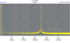
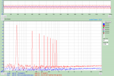
Here are two plots from the RTX using my KH4400a as a source. It has pretty uniform harmonics as you can see. As the harmonics of the source get close to the internal harmonics of the analyzer you do get additions and cancellations. My guess is that below around -125 dB you should be less confident of the absolute level of the harmonics.
The second plot was a much higher (4X) resolution than the first plot so you can see deeper into the noise and more of the power line harmonics are visible.
The second plot was a much higher (4X) resolution than the first plot so you can see deeper into the noise and more of the power line harmonics are visible.
Attachments

Hi Demian,
How much work did it take to allow these low level measurements? I suspect you have modified your lab area to minimise local EMI.
-Chris
How much work did it take to allow these low level measurements? I suspect you have modified your lab area to minimise local EMI.
-Chris
Huh?
And how is it that the ADC/DAC signal chain would only perform even harmonic suppression [vs. odd harmonics] below some threshold value... be it -125dB or otherwise?
Here are two plots from the RTX using my KH4400a as a source. It has pretty uniform harmonics as you can see. As the harmonics of the source get close to the internal harmonics of the analyzer you do get additions and cancellations. My guess is that below around -125 dB you should be less confident of the absolute level of the harmonics.
The second plot was a much higher (4X) resolution than the first plot so you can see deeper into the noise and more of the power line harmonics are visible.
And how is it that the ADC/DAC signal chain would only perform even harmonic suppression [vs. odd harmonics] below some threshold value... be it -125dB or otherwise?
At low levels where the harmonics are similar in levels depending on the phase relationships they can cancel or add. Thats why you really need a source / analyzer that's 10 dB better than a DUT to get accurate values. All of these measurements below -120 dB are more academic than meaningful in terms of any conceivable perceptible effects.
There is no deliberate suppression of the even harmonics!
The hum from the power supply does indeed show more odd harmonics content than even. I have not investigated this in detail, since the levels are rather low.
The power supply has three rectifiers and large capacitors. Two for the 2x15V AC from the transformer and one for the 9V AC. The 2x15V AC are used to deliver +/-15V for the amplifiers via sets of voltage regulators. The 9V AC is used for some of the lower supply voltages.
Perhaps the three rectifiers together generate an amount of 150 Hz etc. ? I am just speculating here since, as mentioned, I have not pursued the issue in detail.
It could be that, due to the balanced design of the input amplifier, the even harmonics of the power supply crosstalk are suppressed. This does not mean though, that harmonics of the test signal will be suppressed. Harmonics may be suppressed, as Demian explains, if the levels of the harmonics in the test signal are at a level similar to the harmonics of the amplifier and they are out of phase. But they could also become stronger, if they are in phase.
Hhhhhmmmmmmm.....
Do not recall making such an assertion, but did speculate that the circuit topology might well have that 'feature'. In no way am I contesting the intent of the designer(s)... just musing about apparent [unforeseen?] side effect(s).There is no deliberate suppression of the even harmonics!
How would it 'know' which signal is PS in origin and which is DUT signal?The hum from the power supply does indeed show more odd harmonics content than even. I have not investigated this in detail, since the levels are rather low.
The power supply has three rectifiers and large capacitors. Two for the 2x15V AC from the transformer and one for the 9V AC. The 2x15V AC are used to deliver +/-15V for the amplifiers via sets of voltage regulators. The 9V AC is used for some of the lower supply voltages.
Perhaps the three rectifiers together generate an amount of 150 Hz etc. ? I am just speculating here since, as mentioned, I have not pursued the issue in detail.
It could be that, due to the balanced design of the input amplifier, the even harmonics of the power supply crosstalk are suppressed. This does not mean though, that harmonics of the test signal will be suppressed.
Agreed and indeed inevitable, but a separate issue from equal treatment for all harmonics extant in the DUT's signal by the measurement apparatus.Harmonics may be suppressed, as Demian explains, if the levels of the harmonics in the test signal are at a level similar to the harmonics of the amplifier and they are out of phase. But they could also become stronger, if they are in phase.
Last edited:
How would it 'know' which signal is PS in origin and which is DUT signal?
Well, it wouldn't of course. I was just speculating that certain sources of internal crosstalk may couple in a way that would be suppressed, and other sources may not be.
Anyway, there is perhaps a more straight forward explanation.
It could be that the hum seen at the odd harmonics are a result of nonlinear functions, e.g. the characteristics of the rectifier diodes in the power supply. This will lead to pulse currents during the charging of the large capacitors of the power supply.
In principle similar to figure 6 here:
http://www.edn.com/Home/PrintView?contentItemId=4422710
I just made a spectrum of a 50 Hz triangle signal. Not quite the same signal as the charge pulse currents, but it was easy to generate with audioTester. This also shows a lot of odd harmonics content and no even harmonics.
The exact source(s) and coupling mechanism(s) are still not investigated, but I think that the levels are low enough for all practical purposes.
Attachments
- Home
- Design & Build
- Equipment & Tools
- DIY Audio Analyzer with AK5397/AK5394A and AK4490