The AK5394A has a noise corner that starts around 80 KHz, almost unique in ADC's. Which HF noise plots do you want (assuming they are in the collection)?
what ever you have that shows the max level and freqs of the noise above audio.
THx-RNMarsh
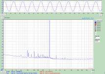
Are you looking for something like this?
I measured this with my Audio Analyzer some time ago. Input range = 10 dBV.
In this case I used a Stanford Research DS360 as the generator. Output level = 2.6 dBV. It was adjusted to give a level of -1 dBFS from the ADC. The noise below 1 kHz is from the DS360. The white noise is gradually disappearing between 1 and 2 kHz due to the low pass filter in the DS360.
As you can see the AK5394A is very clean all the way up to 90 kHz.
Attachments
Hi JensH,
The AK4490 can provide around -116dB THD @ 0dBFS, this is the best performance I can get in my design.
BR
Paul
The distortion I see from the AK4490 based generator is around -105 dB.
In an attempt to improve this I tried to add a large decoupling capacitor on the reference supplies, but it didn't change the distortion.
I wonder if the distortion could be common mode distortion from the op-amps in the post-DAC filter. A use LME49720 for this. To increase the dynamic range I have set the analog supply for the DAC at 7V instead of the usual 5V. This will probably increase the common mode distortion because of the higher output level from the DAC.
Some of the options I am considering to try are:
1. A better op-amp, with less common mode distortion. But which (preferably a dual, since this will make it easier to test in the current layout).
2. Reduce the reference voltage from 7V to 5V.
3. Use boot strap on the op-amp supply.
In principle it could also be the AK4490 itself, which generates more distortion with a 7V supply. But the AK4495 seems to perform better with a 7V supply than with a 5V supply, so I would assume that the AK4490 behaves in a similar way. But at the moment I haven't verified it.
Does anyone have any experiences/opinions on this?
Anyone know if the UR22mkII uses these chipsets?
It is an interesting box, similar to 1616m, I don't know if
it is all self contained...yes, as it says USB audio.
From what I've heard the Steinberg software is
supposed to be pretty robust.
Here is a link:
UR22mkII:|http://www.steinberg.net/
Anyone try this for audio testing?
It is an interesting box, similar to 1616m, I don't know if
it is all self contained...yes, as it says USB audio.
From what I've heard the Steinberg software is
supposed to be pretty robust.
Here is a link:
UR22mkII:|http://www.steinberg.net/
Anyone try this for audio testing?
Recording Simplified, Test Tones?
This is interesting.
It looks to cost about 149.00 USD.
What intrigues me with the simplicity of it
you could have your oscillator tones captured
on the tracks simply,
Say
100 Hz
1000 Hz
1125 Hz
1200 Hz
10 K Hz
Then play them back or loop into say ARTA, QA400
or something else, single tones notched, combined
frequency tracks, pairs, triplets, quads, for those IMD and other measurements.
Instead of lots of time developing software etc,
it is good enough to do analysis?
Basic software is included,
and looks simple enough that
maybe even I could use it.
Here is a link to their demo:
UR22mkII:|http://www.steinberg.net/
Interesting.
Of course then I read the thread title...DIY not trying to say Hi Jack.
Last edited:
Jens:
I think I sent you an alternative passive reconstruction filter that addresses some of these issues. For the existing filter use as low Z as you can and match the impedance on + & - inputs of the opamp. The datasheet (AKD4490: http://www.akm.com/akm/en/file/ev-board-manual/AK4490EQ.pdf ) shows very low impedances -220 Ohms so maybe you can even get lower. An additional small difference is lower distortion with 22.5792 Mhz clock than 24.576 MHz. It has something to do with tuning of internal caps they said. . . I measured from the demo board and have not tweaked it yet, too busy.
I think I sent you an alternative passive reconstruction filter that addresses some of these issues. For the existing filter use as low Z as you can and match the impedance on + & - inputs of the opamp. The datasheet (AKD4490: http://www.akm.com/akm/en/file/ev-board-manual/AK4490EQ.pdf ) shows very low impedances -220 Ohms so maybe you can even get lower. An additional small difference is lower distortion with 22.5792 Mhz clock than 24.576 MHz. It has something to do with tuning of internal caps they said. . . I measured from the demo board and have not tweaked it yet, too busy.
Demian,
Yes, you did. I will dig it out and look at whether this could be a better solution. Or whether I should pursue some of the other options.
Yes, you did. I will dig it out and look at whether this could be a better solution. Or whether I should pursue some of the other options.
@SyncTronx,
I have a UR22 and as far as I remember, is the performance not that great. Can't remember which chips it uses.
I think QA400 is a better option compared to that.
We better stop polluting Jens's thread.
Mogens
I have a UR22 and as far as I remember, is the performance not that great. Can't remember which chips it uses.
I think QA400 is a better option compared to that.
We better stop polluting Jens's thread.
Mogens
@SyncTronx,
I have a UR22 and as far as I remember, is the performance not that great.
These test results seem to agree with you:
RightMark Audio Analyzer òåñò : Yamaha Steinberg USB ASIO
I think QA400 is a better option compared to that.
agreed
These test results seem to agree with you:
RightMark Audio Analyzer òåñò : Yamaha Steinberg USB ASIO

Whatever soundcard alike engine we decide on my wishes beyond the engine is here http://www.diyaudio.com/forums/tube...terface-ideas-suggestions-10.html#post4533036
Regards
Regards
The distortion I see from the AK4490 based generator is around -105 dB.
In an attempt to improve this I tried to add a large decoupling capacitor on the reference supplies, but it didn't change the distortion.
I wonder if the distortion could be common mode distortion from the op-amps in the post-DAC filter. A use LME49720 for this. To increase the dynamic range I have set the analog supply for the DAC at 7V instead of the usual 5V. This will probably increase the common mode distortion because of the higher output level from the DAC.
Some of the options I am considering to try are:
1. A better op-amp, with less common mode distortion. But which (preferably a dual, since this will make it easier to test in the current layout).
2. Reduce the reference voltage from 7V to 5V.
3. Use boot strap on the op-amp supply.
In principle it could also be the AK4490 itself, which generates more distortion with a 7V supply. But the AK4495 seems to perform better with a 7V supply than with a 5V supply, so I would assume that the AK4490 behaves in a similar way. But at the moment I haven't verified it.
Does anyone have any experiences/opinions on this?
I got the lowest distortion from an EBAY sourced AK4490 DAC with a lowly 5532. Beat OPA1612 and LM4562, amongst others.
I would guess AD797 will be lowest distortion as a follower but it's a single and may require additional components to make it stable @ unity of course.
You could try ADA4898-2 also.
You could try ADA4898-2 also.
I am using a CS4398 as the signal generator for by distortion analyser.
I had to move from a single op-amp filter / differential to single ended circuit to a fully differential one to get really good performance. The circuit I used was actually very similar to the AKM one published for the AK5394. I did put a lot of care into matching resistances in the differential to single ended converter.
I have built four of these, using LM4562 op amps on two and NE5532 on two. Both these implementations give 118-120dB THD in loopback with a CS5381 ADC - noting some selection of output level. I couldn't say for sure where the limitation is.
I found a similar lack of noticeable difference in op amp selection for the CS5381 ADC - with both NE5532 and LM4562 delivering similar performance. (note all measurements have been made using a differential front end - which uses multiple NE5532's in parallel - this itself may be defining the lower measurable limit!)
I have been fairly busy lately, so not much progress. I have a few minor changes that I plan to do. And I have started looking at a model for manufacturing and sales.
And I have started looking at a model for manufacturing and sales.
I may be able to help.
-RM
- Home
- Design & Build
- Equipment & Tools
- DIY Audio Analyzer with AK5397/AK5394A and AK4490