Hello
There is a Rane note thate dicusses this problem ( I hope it has not already been mentioned in this thread) , and its about Grounding and Shielding Audio Devices and it gives some insight about Signal ground and Case chassis connection and makes a proposal about connectiing at one point using a star inside the case.
Grounding and Shielding Audio Devices
Usually, I spend my time with the RTX, with Dac's measurements without any significant problem.
Now, I started with the amps and I think so that I have a ground issue.
My setup is : RTX and Personal Computer at the same main power outlet.
The left SE (bnc) signal output of RTX is set to the 10V range and goes out to the Frex's attenuator (one channel) with a bnc (50 Ohm cable)->the output of Frex's attenuator split with a BNC adaptor to the two RCA cables that go to the input of final amplifier->the output of each channel of amp goes to a separate dummy load->from the dummy load a xlr cable goes to the RTX's ADC inputs with the Pin2 & Pin3, the Pin1 is not connected to the dummy load only to the screen of xlr cable.
The SE signal generate output of RTX is set to the 2Vrms exactly and the volume control to the final amplifier is done with the Frex's attenuator.
With no any input signal, I have a pattern noise level that reminds me a common noise issue. The same pattern there is combined with the signal of course.
The RTX main earth is connected on outlet, normally.
The power supply of Frex's attenuator is a Rigol PSU with main earth connected on outlet, normally.
The main earth of final amplifier is connected to chassis, but the gnd signal is not connected on chassis.
I have done some tests with the Pin1 of xlr cable to joined with the amp's chassis, but with no success. I have removed the Frex's attenuator but the same pattern.
Is there any suggestion?
Attachments

It looks like a ground loop issue.
Is protective earth connected to the final amplifier as well as the RTX6001 (from the power outlets)?
In that case hum will be present. The BNC outputs of the RTX6001 are connected to the chassis and thereby also to the protective earth. Using the differential input of the analyzer to measure the signal on the dummy load is OK, but the problem is probably in the input side of the final amplifier.
Have you tried to connect a short thick wire between the ground connection on the front of the RTX6001 and the chassis of the final amplifier? It may reduce the hum. But it will not completely eliminate it.
It looks like a ground loop issue.
Is protective earth connected to the final amplifier as well as the RTX6001 (from the power outlets)?
-Yes, they are.
In that case hum will be present. The BNC outputs of the RTX6001 are connected to the chassis and thereby also to the protective earth. Using the differential input of the analyzer to measure the signal on the dummy load is OK, but the problem is probably in the input side of the final amplifier.
JensH said:Have you tried to connect a short thick wire between the ground connection on the front of the RTX6001 and the chassis of the final amplifier? It may reduce the hum. But it will not completely eliminate it.
I done some experiments with that, today.
Four cases examined
AmpEOff_RTXENoConn.= that means I removed the Earth from the Amp chassis and I haven't any connection between RTX Earth and Amp.
AmpEOff_RTXEConn.= that means I removed the Earth from the Amp chassis and I have a connection between RTX Earth and Amp.
AmpEOn_RTXENoConn.= that means I have joined the Earth from the Amp chassis and I haven't any connection between RTX Earth and Amp.
AmpEOn_RTXEConn.= that means I have joined the Earth from the Amp chassis and I have a connection between RTX Earth and Amp.
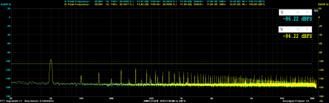
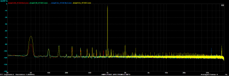
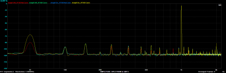
As you can see at the attachement photos, only at the (1) situation, I had an improvement with 50Hz hum by the 18-20dB. But the rest of pattern still the same.
The first was a 192KHz capture, the second is the zoom from 20Hz-2K
Attachments
Did you place the Amp close to the RTX6001? I wonder if it could be noise radiated by the mains transformer of the Amp. Could you try to move the Amp further away?
You could try if the routing of the cables has some influence. I experienced pick up of the environmental mains hum especially if the area bordered by the cables from and back to the RTX6001 was large - even with a floating, battery powered RTX6001.
@JensH = The Amp is on the top of lab table and the RTX on the shelf about 80cm more high from the table.
@zfe = I search anything...
@zfe = I search anything...
...means I removed the Earth from the Amp chassis and I haven't any connection between RTX Earth and Amp...
I am not quite sure what this really means, but...
(1) I guess you diconnected the safety earth connection at the amp. Don't. It's dangerous.
(2) Even if you disconnected the safety earth at the amp, you still have a an "earth" connection via the shield/cold of the BNC output of the RTX.
Suggestions:
(1) If you have ground-loop issues related to safety earth, think about using a ground-loop breaker (see Rod Elliott pages for instance)
(2) Can you use the balanced output of the RTX, thus avoid mixing earth and signal?
See here: Tutorial: How to use the RTX6001 audio analyzer in real world audio tests
Hi mbrennwa,
That looks useful, I'll have a read.
I generally run my DUT from an isolated variac. The ground in this equipment is also lifted (not by me! It's the design of the unit, B & K 1655 AC Power Supply.
That looks useful, I'll have a read.
I generally run my DUT from an isolated variac. The ground in this equipment is also lifted (not by me! It's the design of the unit, B & K 1655 AC Power Supply.
@mbrennwa : yes you right guess, I disconnected the safety earth connection for a quickly test.
(2) you have right
About your suggestions. For the first - ground loop braker - I think to must use a Lundhall trafo (LL1545A) btw the bnc and the input of amp to see what will be happening.
I had used the xlr output of RTX (Pin2 and Pin1) but I had no success..
(2) you have right
About your suggestions. For the first - ground loop braker - I think to must use a Lundhall trafo (LL1545A) btw the bnc and the input of amp to see what will be happening.
I had used the xlr output of RTX (Pin2 and Pin1) but I had no success..
About your suggestions. For the first - ground loop braker - I think to must use a Lundhall trafo (LL1545A) btw the bnc and the input of amp to see what will be happening.
Yes, a transformer would break the loop. However, I was referring to this Earthing (Grounding) Your Hi-Fi - Tricks and Techniques
First step disconnect the connection between the amp and the RTX and short it to get a baseline. That 50 Hz will be a baseline. If its high you need to address that first. Moving that cable around will show local hum fields to avoid. To check for radiation from the amp transformer etc. you can start with no power to the amp and see how much 50Hz you get. Then disconnect the power cord and see which way the hum goes. Also with the amp connected to power, both grounded and not grounded measure the voltage between the amp chassis and the RTX. You can also measure across a 1K Ohm resistor between the two chassis to see how much leakage current there is. leakage current is the most insidious since it will go through the RTX and 'pollute' all the ground connections.
Demian, thanks for all your suggestion.
- For the first, I take a Noise Baseline capture without amp on, all the cabling is on.
- This amp has a ground loop braker at the relay input, with a series of 47.5R and 220nF btw gnd signal and earth safety (case1).
With this setup without signal and no connection btw RTX and Amp I take a shot of Noise Baseline with the Amp on.
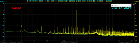
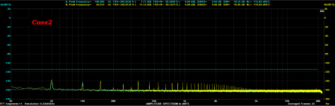
Then I removed this ground loop braker and put a parallel 10R with 100nF capacitor (case2).
With this new ground loop braker, without signal (input bridged) I had the best results on Noise Baseline.
But the things are strange when I give a signal from RTX.
Compare the THD@1KHz at the 1W@8 Ohm, btw case1 and case2. I feel that the case1 has better pattern.
First step disconnect the connection between the amp and the RTX and short it to get a baseline. That 50 Hz will be a baseline...
- For the first, I take a Noise Baseline capture without amp on, all the cabling is on.
- This amp has a ground loop braker at the relay input, with a series of 47.5R and 220nF btw gnd signal and earth safety (case1).
With this setup without signal and no connection btw RTX and Amp I take a shot of Noise Baseline with the Amp on.
Then I removed this ground loop braker and put a parallel 10R with 100nF capacitor (case2).
With this new ground loop braker, without signal (input bridged) I had the best results on Noise Baseline.
But the things are strange when I give a signal from RTX.
Compare the THD@1KHz at the 1W@8 Ohm, btw case1 and case2. I feel that the case1 has better pattern.
Attachments
-
 THD @44.1KHz, 1W, 8 Ohm, new grnd loop braker - Case2.png30.4 KB · Views: 487
 -
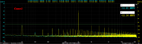 THD @44.1KHz, 1W, 8 Ohm - Case1 diy.png33 KB · Views: 490
 -
 Noise Floor Amp On, Input bridged - Case2 diy.png25.6 KB · Views: 505
 -
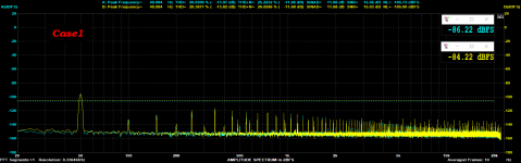 Noise Floor Amp On, Input bridged old ground loop braker - Case1 diy.png31.7 KB · Views: 488
 -
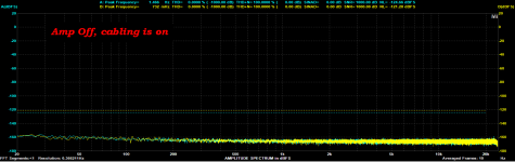 Noise Floor Amp Off, diy.png26.2 KB · Views: 499
Last edited:
1audio said:Also with the amp connected to power, both grounded and not grounded measure the voltage between the amp chassis and the RTX.
- Amp connected to the power and on, not grounded btw RTX chassis and Amp chassis, the voltage AC measured 0.56mV
- Amp connected to the power and on, grounded btw RTX chassis and Amp chassis, the voltage AC measured 0.14mV
1audio said:You can also measure across a 1K Ohm resistor between the two chassis to see how much leakage current there is. leakage current is the most insidious since it will go through the RTX and 'pollute' all the ground connections.
- I saw a current almost 0.03mA with a Fluke45 multimeter.
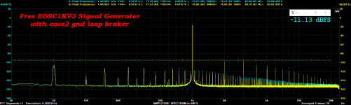
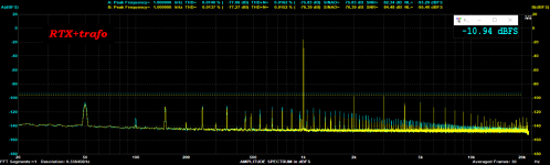
Also, I connected the Frex EOSC1KV3 Signal Oscillator and took a shot at 1W@8 Ohm.
The Noise Pattern is more smoothing in case2 like at the case1 of ground loop braker.
Attachments
Last edited:
Yes, a transformer would break the loop. However, I was referring to this Earthing (Grounding) Your Hi-Fi - Tricks and Techniques
I done and this measurement, a trafo SE->SE on RTX output.
There is no any improvement on Noise Pattern and I am thinking your thought at the "Tutorial: How to use the RTX6001 audio analyzer in real world audio tests", that you said :
"There are also a number of peaks at 50 Hz, 100 Hz, 150 Hz, etc. This might point to pickup of mains power noise in the amplifier or by the measurement setup (although there should be no ground loop in the test setup). Some of these peaks are higher with lower dummy loads. This might point to increased ripple in the linear power supply of the power amplifier when the output current is higher with lower dummy loads."
Attachments
i found a very worthwhile improvement using canare star quad cabling ($2/m here iirc) -
posted the before/after pics here: Low-distortion Audio-range Oscillator
(post #6760)
posted the before/after pics here: Low-distortion Audio-range Oscillator
(post #6760)
Thanks for the reminder about Canare Star.
I use this cable to the testing PSRR and Zo, but it is time to make a 1.5m interconnect cable with this.
It is good to EMI/RFI decreased noise, according to the datasheet.
I use this cable to the testing PSRR and Zo, but it is time to make a 1.5m interconnect cable with this.
It is good to EMI/RFI decreased noise, according to the datasheet.
I have a question on the architecture. On the inputs, the level swich can be set up to +20dB. Does that mean that there is an additional gain stage switched in, or is it only a switching-out of attenuation that would be there in the other settings?
Jan
Jan
I remember Jens stating that the 10dBV input setting is the most direct (I assume that this means without attenuation or amplification) and should yield lowest distortion.
In contrast, the -20dBV setting should yield lowest noise.
In contrast, the -20dBV setting should yield lowest noise.
- Home
- Design & Build
- Equipment & Tools
- DIY Audio Analyzer with AK5397/AK5394A and AK4490