Trev,
They are on a website dedicated to the history of wide screen cinema. The link is:
http://www.widescreenmuseum.com/widescreen/miscref.htm
Enjoy. I think these old device's are the perfect answer for DIY projectors. You would be able to use an inexpensive 4:3 high rez LCD and adjust the picture with Power DVD and the adjustable anamorphic lens to optimize any DVD. And utilize all of the LCD's resolution besides. As far as I can tell all of these lenses use prisms and stretch the image from 1:1 to 1:3.
Hezz
These old variable anamorphic lenses used two achromatic prisms.
Meaning that each prism was made up of two different types of glass. Usually a flint and a crown glass. One glass has a high refractive index and dispersive number and the other has a lower reflective index and dispursive number.
They could also be made of two different types of plastic of the right kind.
Hezz
Hi guys, first post here!
Hezz, I sended you a PM(or email), I am not sure you recived it ?!
Anyway, I am making some Anamorphic prototypes at a Numerical CNC company for free, because it is through my father. So machine time etc isn't a problem.
I have tried the above design you descibed using the prism pair (see some picture below) and it works fairly good, however the best would be using some sort of correcting lens at the end(aspherical), because at high magnitudes the design gives some geometry distoration.
Also if using only the two prism, the offset would change some 0.XX %.You can archive the anamorphic magnitude using only one prism (not the same design with 90,60,30) but then you need AR coating.
There is some "color" Astigmatism at ther very rear end of the screen(not anonoying for typical screen width). If not using mirrors, this is hard to make even less, if not caoting.
i have also tried some spherical shaped curvates and it works good.
Before i started i was talking to a lecture here at Chalmers University of Technolgy in Sweden(were I study) and found a sort of PMMA polymer with very accurate optical performence.Which I now use.Ordinarey PMMA seems to be in the 90-92 % range, this one is higher.
Now, i want to reduce the elements in the design, because the light tranmission is defined on 2 surface hit. Using Aspherical lens design, you can aprrox. say that one lens is giving you the result of two spherical(if you assume you can hold the toleranace and surface roughness low). That makes a lightweight and compact lens, with high light tranmssion plus few geometry errors.
A aspherical lens, is actually given by the parabolic f(x) function.
however I can not figure out the correct radius and focal lenght f.
fot he multiple elements(mabey that is what you all are talking about in this thread..=))
Hezz, you were using Zemax earlier, any chance of helping me on this one ?
Or anyone else ?
Yeah, the dream would be using a variable lens and that is not so tricky with some triplets, hower it makes the magnitude even worse so it's critical for not introducing barrel or pinchusion, but with high precion aspherical lenses, it would work.
And the CNC molding with all thoose free axis is sure enough to keep the surface correct.
Isco are using a 4 elements design, spherical/cylindrical, prismasonic panamorph using prism pair. But all thoose commersial lenses cost $$$(for such a optical design).
I can help you maching/molding lenses, if you helping me figure out the design. Otherwise i need to keep the trial and error (aspherical) lens design. And *lol* i am running out of material currenly but I will get new this week.
i haven't done any box/lens objective, hower that's the smallest problem, you just using some Re-engineering on Isco Lens design =)
Some photos
can you detect the prism?, good tranpacary on this one =)
here
]pictures
dunno, know's why the link above dosen't wirk correcly, it has something to do with the brackets. put an " ] " at the end of the name Aero[CTH in you browser.
Hezz, I sended you a PM(or email), I am not sure you recived it ?!
Anyway, I am making some Anamorphic prototypes at a Numerical CNC company for free, because it is through my father. So machine time etc isn't a problem.
I have tried the above design you descibed using the prism pair (see some picture below) and it works fairly good, however the best would be using some sort of correcting lens at the end(aspherical), because at high magnitudes the design gives some geometry distoration.
Also if using only the two prism, the offset would change some 0.XX %.You can archive the anamorphic magnitude using only one prism (not the same design with 90,60,30) but then you need AR coating.
There is some "color" Astigmatism at ther very rear end of the screen(not anonoying for typical screen width). If not using mirrors, this is hard to make even less, if not caoting.
i have also tried some spherical shaped curvates and it works good.
Before i started i was talking to a lecture here at Chalmers University of Technolgy in Sweden(were I study) and found a sort of PMMA polymer with very accurate optical performence.Which I now use.Ordinarey PMMA seems to be in the 90-92 % range, this one is higher.
Now, i want to reduce the elements in the design, because the light tranmission is defined on 2 surface hit. Using Aspherical lens design, you can aprrox. say that one lens is giving you the result of two spherical(if you assume you can hold the toleranace and surface roughness low). That makes a lightweight and compact lens, with high light tranmssion plus few geometry errors.
A aspherical lens, is actually given by the parabolic f(x) function.
however I can not figure out the correct radius and focal lenght f.
fot he multiple elements(mabey that is what you all are talking about in this thread..=))
Hezz, you were using Zemax earlier, any chance of helping me on this one ?
Or anyone else ?
Yeah, the dream would be using a variable lens and that is not so tricky with some triplets, hower it makes the magnitude even worse so it's critical for not introducing barrel or pinchusion, but with high precion aspherical lenses, it would work.
And the CNC molding with all thoose free axis is sure enough to keep the surface correct.
Isco are using a 4 elements design, spherical/cylindrical, prismasonic panamorph using prism pair. But all thoose commersial lenses cost $$$(for such a optical design).
I can help you maching/molding lenses, if you helping me figure out the design. Otherwise i need to keep the trial and error (aspherical) lens design. And *lol* i am running out of material currenly but I will get new this week.
i haven't done any box/lens objective, hower that's the smallest problem, you just using some Re-engineering on Isco Lens design =)
Some photos
An externally hosted image should be here but it was not working when we last tested it.
can you detect the prism?, good tranpacary on this one =)
An externally hosted image should be here but it was not working when we last tested it.
An externally hosted image should be here but it was not working when we last tested it.
here
]pictures
dunno, know's why the link above dosen't wirk correcly, it has something to do with the brackets. put an " ] " at the end of the name Aero[CTH in you browser.
Chalmers,
Great work. I'm glad to see someone working on this. I have access to a computer with Zemax but I havn't figured out how to model prisms yet. I need to study more optical theory but I havn't the budget for the textbooks yet. I will help you in anyway that I can with software modeling of the prisms.
A couple of questions about your aspheric lens surfaces. How can you finish the surfaces with CNC to a high degree of finish. I know that you can cut the surfaces with a high degree of mathmatical accuracy but the problem is the tool itself. It leaves minor scallops on the surface of the lens. Are you using high speed balanced tooling.
One other thought. Although clear polyester casting resin is not usually used for lenses certain kinds have a high index of refraction and relatively high dispersion. It might be a better substitute than PMMA. Also it's a thermoset so you can pour an approximate shape before machining.
I did not recieve your e-mail so perhaps it is my old e-mail address.
The new one is:
pheslington@earthlink.net
Hezz
Some interesting information from a web site:
The Chretian system consisted of a "cylindrical" anamorphic attachment to be placed in front of a normal "prime" lens. All three of the lenses were tested. Typical measurements were a change in squeeze ratio across the screen from 1.87:1 in the center of the screen to 2.04:1 halfway to the edge, and 2.37:1 at the very edge. Furthermore, the ratio changed with focus distance, being 2.50:1 at distances greater than 30 feet (9 meters) and shrinking down to 1.80:1 at 5 feet (1.6 meters). When projected at a constant 2:1 squeeze ratio, an actor walking across the screen would become thinner near the edge of the screen, and when photographed in close-up, his face would become fatter.
At the same time, Fox asked Bausch & Lomb, an American lens-manufacturing company, to manufacture 250 cylindrical camera attachment lenses as quickly as possible. Although the early Bausch & Lomb attachment lenses were poor and eventually had to be scrapped, those made by Zeiss for Warner's SuperScope system were worse by comparison.
In 1954, Panavision founder Robert Gottschalk owned a camera store in Westwood Village, where his customers included many professional photographers and cinematographers. Among his acquaintances was an optical engineer, Walter Wallin, who helped him design a prism-type de-anamorphoser that proved to be far superior to the original CinemaScope cylindrical-type projection lenses. Ironically, Gottschalk and Wallin's lens was based on an even earlier Chretian development.
The advantages of the prismatic system of anamorphic attachment lenses were that they were far simpler and less expensive to manufacture, and if the prisms were mounted so that they could be swiveled together, the anamorphic squeeze ratio could be modified. It could easily be set to be 2:1, 1.50:1 and even 1:1 and would remain even and optically true all across the screen.
Hezz
Hi Hezz! thx for posting,
Sorry for being so slow on reply, I have three exams next week, so i can't work on the lens 24/7 🙁
Intresting reading about the Panavision design indeed.
Yeah, we were using a high speed milling jig on the spherical shape, "they" (the operaters) had been working on some plastics material before, it is very crucial in regards to the cutting speed but also the feed rate in the Z lathe, depending very much of the ductile(E modul) properties of the material.
It can reproduce a Ra surface roughness within the <10^-6 m range, however you are right concering the Aspherical shape and the higher demanding of the grinding tolernace.
Ra quality is evertything indeed, but in this stage it's almost like rapid protoyping till I find a fully working concept.
ofcourse i will post everything here, cutting speed, ProE/CAM, dimensiosn etc.
I am not sure which sort of maching the pro using on the ASPH lens polishing, tools etc.
They had some gridning surface tool, effect like a "p2000" paper with oil cutting.
mabey I just should go with the spherical shape and make the entire lens correct. And then start thinking about ASPH lenses.
Anyway, I bought some new material today, so hopefully we can continue maching on friday. Thanks for ther material suggesteion, I will try to find it.
Oh, btw. i just found a post you made with a anamorphic/zoom sketch
http://www.diyaudio.com/forums/showthread.php?s=&threadid=25171
Do you think it would be woth trying, or have you come up with new ideas =)
It think it is pretty hard telling the Radius on the Collimator lens, if we don't have the knowldege of the "fast cone" from the projector lens.
I do like your idea!, the tricky part is finding the two different offset focal lenght. Some pages i found, list focal lenghts on a 2X squeeze factor.
the colliamtor lens should be almost the same in dimension as the projector lens, from there we can start calculate every other lens, given Max/Min squeeze your variable lens can give.
Chalmers,
Good to hear from you. I have done a little research on micromachining since I last posted and now I know how they machine those high tolerance aspheric lenses. They can get very high surface finish with single point diamond maching and a special CNC machine that has ultra high precision. These are not typical CNC machines. They have forced air or oil bath bearings and special high resolution ball screws.
Anyway I think that my idea for variable anamorphic lens would work but it would introduce lots of abberations errors unless they where aspheric surfaces. From all that I have read so far it seems the large prism type anamorphic lenses have the least amount of distortion. One good thing though is that if the lenses are made of solid plastics they should be able to be thinner than the water / mineral oil lenses that Tor made since they will have a higher index of refraction.
That sketch was not intended to be accurate from a real design point of view in was just an idea but keep working on your prisms they should be awesome.
Hezz
Anyone try using a dual cylindrical plano convex-plano concave design?
I ordered cylindrical lenses here
http://www.einsteins-emporium.com/science/l-optics/sl230.htm
and also some rectangular acrylic prisms from the same company.
Now i wonder if I will be able to fit the light beam from the PJ (Optoma H30) into the 2inch by 2 inch surface. Time will tell.
Hopefully these have a nice surface finish...
If not, my cousin can use them as optics teaching tools.
MarcoT,
Of course there are other ways to create an anamorphic lens. From what I have been able to gather so far from my research on the internet. And it has been difficult because there is not a lot of hard core technical information on anamorphic lens design. There are several approaches. The makers of the old variable anamorphic lens chose to use prisms because they caused the least amount of distortion and abberations to the image. And by rotating the lenses they could change the compression or expansion ratio within certain limits without too much serious abberation being introduced into the projection lens system.
If you are designing an anamorphic lens with a fixed compression ratio meaning that the lenses do not move then you could use some kind of lenses like you describe with other lenses to correct for abberations. In order to get the plano cylindrical lenses to work and project a really good image you will have to introduce other correcting lenses into the system.
The modern trend is to make a specialized aspherical lens than can compress or expand the image but this requires a lot of math and very expensive machining on ultra high micro precision CNC maching tools.
If you are concerned about image quality the prisms are actually the best way to go. They are also easier to make than cylindrical lenses. The biggest problem that I see with these cylindrical lenses is that they are not achromats meaning that they have a lot of chromatic distortion. They will only focus one wavelenth of light properly. Chromatic distortion does not just change color properties but effects the focusing quality of the image.
Hezz
Hi Hezz,
Some people have had success reducing or eliminating the chromatic aberration with 2 prisms or lens made with the same material. This is what I am trying out now.
Check out the slize build, with 2 oil prisms.
Some people have had success reducing or eliminating the chromatic aberration with 2 prisms or lens made with the same material. This is what I am trying out now.
Check out the slize build, with 2 oil prisms.
Guys,
I have been doing some research in the patents and I have gathered this short document with some history and information to prismatic variable anamorphic lenses.
Here is the attachment. It is a txt document created in wordpad.
The end of the document lists the U. S. patent numbers that are most pertinent to this.
Hezz
Attachments
Guys,
After some study of the patents and of Torne's lenses I have come to the conclusion the the prismatic types of variable anamorphic lens are impratical for large aperture lenses. The prisms are way too large and heavy to work with the DIY triplet that I want to build. It has a final lens of nearly 6 inches in diameter.
So I have come up with another design based on U.S. patent number 3,751,138. It uses a lens system that will be necessary to build with a CNC machine that can grind the lens as it uses a very special surface correction. I will post a picture of the lens and then give the mathmatical formula that describes the surface according to the author.
This lens though harder to build has some advantages to the prisms. First the same configuration can be used to both expand the image horizontally and compress it vertically. The mount will be easier to build.
It will be made as a triplet trio for more chromatic abberation correction.
Here is a gif image of what the lens surface looks like. Two of these lenses are needed at minimum and one is the exact opposite of the other one so that they fit together to make one virtual flat of glass. Each piece can be of a different type of glass.
The three peice method allows for some more abberation correction for wider angle lenses. Instead of two there are three pieces. The middle one has the surface on both sides of opposite polarity. And then the outside lenses are fitted with the same surface so that all of the lenses fit together to make one virtual flat. When the middle lens is moved up or down perpendicular to the lens imaging axis the image is either compressed or expenaded depending on which direction you move the lens.
Hezz
Attachments
While the lenses must be made so that all of the opposing surfaces are mirror opposites of each other so that the lenses could actually be placed next to each other to form one flat plate the lenses are actually seperated enough so that one of the lenses can be moved without hitting the other ones.
With the three lens system the middle one would be best to make movable I think.
When the lenses are aligned the net magnification is zero except for the refraction of the glass itself.
Now I feel that a negative spherical radius could be made in the first lens and a positive sherical radius on the last lens of exactly equal radius. This should improve the lens performance but still maintain the net overall magnification of zero. Or nearly zero. The negative curve on the first surface will cause less light loss because most of the light rays are exiting the objective lens at an angle will strike the negative surface at a more normal angle than if the surface was flat.
The idea is that this lens system is placed after the normal objective lens system.
I will post a picture of a rough 3D model that is not perfect as far as the correction surface is concerned but to give an idea of what I mean.
The way to get the surface is to have a software application that can derive a high resolution surface from the equation plot the surface. Then the surface information needs to be saved in a high resolution IGES format and imported into a CAM software package.
I know the Mathematica can export a DXF of a formula derived surface but DXF wouldn't have enough resolution for the CAM software. Does anyone know if newer versions of MathCAD, Maple or Mathematica can expert a formula derived surface in IGES or other high resolution format. Or is ther any other software that can do it.
Hezz
Here are some more images. The lenses are actually moved sideways in relation to each other rather than turned or moved apart. Also ideally the surface correction would be small compared to the picture so that fewer distortions are created. The pictures are exaggerated to show the surfaces.
Hezz
Hezz
Attachments
OK,
Here is a quick model of my idea. The three lenses don't have exactly the right surface but close enough to show the idea. The first lens has a negative spherical surface and then the anamorphic surface. The negative surface is hard to make out.
Hezz
Here is a quick model of my idea. The three lenses don't have exactly the right surface but close enough to show the idea. The first lens has a negative spherical surface and then the anamorphic surface. The negative surface is hard to make out.
Hezz
Attachments
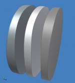
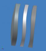
Now from the side to give an idea of the combination. The middle lens is moved up and down to compress or expand the image. When all three lenses are aligned the net magnification is zero.
The lenses will actually be placed closer together to minimize distortions.
Hezz
The lenses will actually be placed closer together to minimize distortions.
Hezz
Attachments
It is important that the first negative surface and the last positive surface have the same radius. Then the three lenses can be made of differing glasses or materials to correct for the color abberations just like in the cooke triplet.
The radius of the neg and pos surfaces can be chosen to minimize angular distortions from the emerging light rays from the objective.
I may have to think on this some more but it is possible that the middle lens surfaces may need to be reversed in order to work properly. What matters is that the sum total of magnification through the system is zero.
Hezz
Attachments

- Home
- General Interest
- Everything Else
- The Moving Image
- Optics
- DIY anamorphic lens