Btw, I don't mind it is off the topic if you can share the design of your decks suspension/isolation.
Hi Jim.
Sorry I missed this post. I've been a bit busy with my own bearings of late. I've got a couple of things on my list but will put together an explanation soon. The suspension system is quite simple. The concept and interactions make finding the best starting point for the explanation difficult.
Niffy
It is fine. Take your time.
I am making an aluminum head shell now and will post the result once it is done.
Jim
I am making an aluminum head shell now and will post the result once it is done.
Jim
Suspension description
Hi Jim.
The purpose of a suspension system on a record player is to isolate it from external sources of vibration. These can be from many sources, vehicles passing outside, people walking, water in pipes but mainly from the speakers.
With a conventional suspension deck the arm and platter are mounted on a subchassis that stands on or is hung from some form of springs. The motor is either directly mounted to the decks plinth or is a completely separate from the deck in a motor pod. This style of deck has become less popular of late with the solid plinth style of deck becoming more popular. This is mainly due to a major problem with suspended decks that solid models don't suffer. The friction in the main bearing, stylus drag and belt hysteresis all create the torque that the motor has to drive. This torque twists the subchassis on its suspension and sets up an oscillation. The subchassis has a constant shimmy which can often create a problem as great as the one the suspension is aimed to cure. The normal way of combating this shimmy is by damping the suspension.
Damping the suspension seems like a good idea as if you bounce the suspension you want the deck to come to rest quickly. This view of how the suspension works has a fundamental flaw. It uses the plinth/ground as the reference point to which the subchassis is bought to rest. It is the vibrating ground that you are trying to isolate the subchassis from. The whole point of the suspension system is that the subchassis is kept stationary whilst the plinth/ground bounces and vibrates. The stationary subchassis should be the reference point. This is an easy mistake to make. Probably the best after market isolation platform is the minus K. Their website shows an animation of how their system works. Even in this the platform is moving whilst the base is stationary. Completely the opposite of what you want.
By damping the suspension what you are actually trying to do is bring the entire world to rest relative to the stationary subchassis and that just isn't going to happen. The suspension should be COMPLETELY UNDAMPED. A critically damped systems level of isolation is proportional to the driving frequency. With an undamped system the isolation is proportional to the SQUARE of this frequency.
When using the ground as a reference you isolate the subchassis from the ground, you attach the motor to the ground and then attach the motor to the subchassis with the belt. This is as open system.
By using the subchassis as the reference you isolate the ground from the subchassis and you isolate the motor from the subchassis. In other words you mount the motor on the subchassis. This creates a closed system, there is no interaction between the suspended deck and the outside world. There will still be a torque reaction between the motor and platter but this cannot effect the main suspension. This torque reaction is controlled by damping the suspension that separates the subchassis from motor. Also reducing the level of bearing friction reduces the torque and reduces this torque reaction.
"what about motor vibration" I hear you scream.
First imagine that you have a very noisy motor. In this case you would want to get the motor as far away from the deck as possible and use a long stretchy belt. Now imagine that you have an absolutely silent motor. Now you can attach the motor directly to the subchassis with out any fear and use a short belt. If the motor has a little bit of vibration a little bit of isolation would be needed. Above some level of motor noise it is better to have a separate motor mounting, below that level it is better to mount the motor, via an isolation, on the subchassis. Modern quite running dc motors and power supplies are below the threshold where moving the motor to the subchassis is desirable. On my deck using a mechanics stethoscope and listening for motor noise I cannot detect any at all anywhere other than directly on the motor itself.
Many idler drive decks and all direct drive decks have the motors directly attached to the platter usually without adverse noise. All solid plinth decks have the motor directly attached to the plinth/chassis even if it is only by the shelf the deck is stood on. If you stand a solid plinth deck on an isolation platform the plinth becomes the subchassis with the motor mounted on it. Mounting the motor on the subchassis is a lot more common than at first it seems but most manufacturers don't see it that way. The notable exception is funk/pink triangle.
My deck can be seen as a suspended subchassis design or a solid plinth design with dedicated isolation platform. The plinth and isolation platform being fine tuned to each other. My aim is to get the best of both worlds.
My subchassis hangs from 3 steel coil springs and is completely undamped. Hanging from springs is dynamically more stable than standing on springs and the springs used can be much thinner which reduces energy transfer by sound waves traveling along the wire of the spring. The springs are set equidistant apart on the apexs of an equilateral triangle.
In most decks which hang from springs the springs are not equidistant. The subchassis is levelled by raising and lowering the point at which the spring is attached to the plinth. The load on each of the springs will be different. Changing the tonearm for a different one will change the load distribution. As each spring is supporting a different mass they will all have a different fundamental frequency and their level of isolation will be different. This will cause the subchassis to jiggle at many different frequencies all at once.
The total mass of the platter, arm, motor and subchassis (the entire suspended mass) of my deck has its centre of mass aligned with the centre of the suspension system. The weight is distributed evenly between the 3 springs meaning that the fundamental frequency of each spring is the same and all 3 act as a single unit rather than 3 disparate systems. Additionally my deck levels the subchassis by changing the length of the springs rather than moving them. If the centre of mass isn't exactly aligned with the centre of suspention and the springs are set to the same length the subchassis will slope towards the centre of mass and the fundamental frequencies will be slightly different. Changing the lengths of the springs until the subchassis is level will move the centre of suspension to align with the centre of mass and the fundamental frequencies of the 3 springs will then be the same. This allows for very easy suspension fine tuning. Here's a photo of the very simple spring length adjuster. The suspension is tuned to have a vertical fundamental frequency of 3hz. By the nature of how a mass suspended on a spring moves the lateral fundamental frequency is half this at 1.5hz.
As I was building the deck I started on the arm then the platter, bearing and drive system. Having built these I mounted them on a temporary plinth. Then I tinkered and tweaked until I had the best sounding design. I then weighed them and measured where their individual centres of mass were. Using this information I then tweaked the subchassis design until the centre of mass aligned with the centre of the suspension system. I also, at this point, made sure that the motor sat at the centre of the decks suspension. This ment that the centre of suspension of the motors suspension system is perfectly aligned with the centre of the decks suspension. This helps to further reduce any negative interactions between the two.
I then built the subchassis, the design of this is a subject for another time. The subchassis with platter, arm and motor fitted was at this point a solid plinth deck and was used as a solid plinth deck for about a year. Here are some photos of the deck at that time. I bolted spiked feet into what were to become the suspension attachment points. I've also included a photo of the cardboard template that I used whilst determining the subchassis's centre of mass.

If I were to just hang the deck as it was then from springs the centre of mass would have been way above the points where the springs attached. Any lateral movement would cause the subchassis to rock back and forth. The solution to this also has another big role to play that I will describe afterwards. A heavy counterweight is hung under the subchassis. This drops the centre of mass of the entire suspended mass to be level with the points where the springs attach to the subchassis. Having the centre of mass perfectly aligned with the centre of suspension make it very stable and maximizes its isolation performance. The counterweight sit in a recess within the lower plinth section and is not normally visible. Here are some photos. The first is of the subchassis/counterweight assembly removed from the deck. The next few shows the counterweight and its recess.


Hi Jim.
The purpose of a suspension system on a record player is to isolate it from external sources of vibration. These can be from many sources, vehicles passing outside, people walking, water in pipes but mainly from the speakers.
With a conventional suspension deck the arm and platter are mounted on a subchassis that stands on or is hung from some form of springs. The motor is either directly mounted to the decks plinth or is a completely separate from the deck in a motor pod. This style of deck has become less popular of late with the solid plinth style of deck becoming more popular. This is mainly due to a major problem with suspended decks that solid models don't suffer. The friction in the main bearing, stylus drag and belt hysteresis all create the torque that the motor has to drive. This torque twists the subchassis on its suspension and sets up an oscillation. The subchassis has a constant shimmy which can often create a problem as great as the one the suspension is aimed to cure. The normal way of combating this shimmy is by damping the suspension.
Damping the suspension seems like a good idea as if you bounce the suspension you want the deck to come to rest quickly. This view of how the suspension works has a fundamental flaw. It uses the plinth/ground as the reference point to which the subchassis is bought to rest. It is the vibrating ground that you are trying to isolate the subchassis from. The whole point of the suspension system is that the subchassis is kept stationary whilst the plinth/ground bounces and vibrates. The stationary subchassis should be the reference point. This is an easy mistake to make. Probably the best after market isolation platform is the minus K. Their website shows an animation of how their system works. Even in this the platform is moving whilst the base is stationary. Completely the opposite of what you want.
By damping the suspension what you are actually trying to do is bring the entire world to rest relative to the stationary subchassis and that just isn't going to happen. The suspension should be COMPLETELY UNDAMPED. A critically damped systems level of isolation is proportional to the driving frequency. With an undamped system the isolation is proportional to the SQUARE of this frequency.
When using the ground as a reference you isolate the subchassis from the ground, you attach the motor to the ground and then attach the motor to the subchassis with the belt. This is as open system.
By using the subchassis as the reference you isolate the ground from the subchassis and you isolate the motor from the subchassis. In other words you mount the motor on the subchassis. This creates a closed system, there is no interaction between the suspended deck and the outside world. There will still be a torque reaction between the motor and platter but this cannot effect the main suspension. This torque reaction is controlled by damping the suspension that separates the subchassis from motor. Also reducing the level of bearing friction reduces the torque and reduces this torque reaction.
"what about motor vibration" I hear you scream.
First imagine that you have a very noisy motor. In this case you would want to get the motor as far away from the deck as possible and use a long stretchy belt. Now imagine that you have an absolutely silent motor. Now you can attach the motor directly to the subchassis with out any fear and use a short belt. If the motor has a little bit of vibration a little bit of isolation would be needed. Above some level of motor noise it is better to have a separate motor mounting, below that level it is better to mount the motor, via an isolation, on the subchassis. Modern quite running dc motors and power supplies are below the threshold where moving the motor to the subchassis is desirable. On my deck using a mechanics stethoscope and listening for motor noise I cannot detect any at all anywhere other than directly on the motor itself.
Many idler drive decks and all direct drive decks have the motors directly attached to the platter usually without adverse noise. All solid plinth decks have the motor directly attached to the plinth/chassis even if it is only by the shelf the deck is stood on. If you stand a solid plinth deck on an isolation platform the plinth becomes the subchassis with the motor mounted on it. Mounting the motor on the subchassis is a lot more common than at first it seems but most manufacturers don't see it that way. The notable exception is funk/pink triangle.
My deck can be seen as a suspended subchassis design or a solid plinth design with dedicated isolation platform. The plinth and isolation platform being fine tuned to each other. My aim is to get the best of both worlds.
My subchassis hangs from 3 steel coil springs and is completely undamped. Hanging from springs is dynamically more stable than standing on springs and the springs used can be much thinner which reduces energy transfer by sound waves traveling along the wire of the spring. The springs are set equidistant apart on the apexs of an equilateral triangle.
In most decks which hang from springs the springs are not equidistant. The subchassis is levelled by raising and lowering the point at which the spring is attached to the plinth. The load on each of the springs will be different. Changing the tonearm for a different one will change the load distribution. As each spring is supporting a different mass they will all have a different fundamental frequency and their level of isolation will be different. This will cause the subchassis to jiggle at many different frequencies all at once.
The total mass of the platter, arm, motor and subchassis (the entire suspended mass) of my deck has its centre of mass aligned with the centre of the suspension system. The weight is distributed evenly between the 3 springs meaning that the fundamental frequency of each spring is the same and all 3 act as a single unit rather than 3 disparate systems. Additionally my deck levels the subchassis by changing the length of the springs rather than moving them. If the centre of mass isn't exactly aligned with the centre of suspention and the springs are set to the same length the subchassis will slope towards the centre of mass and the fundamental frequencies will be slightly different. Changing the lengths of the springs until the subchassis is level will move the centre of suspension to align with the centre of mass and the fundamental frequencies of the 3 springs will then be the same. This allows for very easy suspension fine tuning. Here's a photo of the very simple spring length adjuster. The suspension is tuned to have a vertical fundamental frequency of 3hz. By the nature of how a mass suspended on a spring moves the lateral fundamental frequency is half this at 1.5hz.
As I was building the deck I started on the arm then the platter, bearing and drive system. Having built these I mounted them on a temporary plinth. Then I tinkered and tweaked until I had the best sounding design. I then weighed them and measured where their individual centres of mass were. Using this information I then tweaked the subchassis design until the centre of mass aligned with the centre of the suspension system. I also, at this point, made sure that the motor sat at the centre of the decks suspension. This ment that the centre of suspension of the motors suspension system is perfectly aligned with the centre of the decks suspension. This helps to further reduce any negative interactions between the two.
I then built the subchassis, the design of this is a subject for another time. The subchassis with platter, arm and motor fitted was at this point a solid plinth deck and was used as a solid plinth deck for about a year. Here are some photos of the deck at that time. I bolted spiked feet into what were to become the suspension attachment points. I've also included a photo of the cardboard template that I used whilst determining the subchassis's centre of mass.
If I were to just hang the deck as it was then from springs the centre of mass would have been way above the points where the springs attached. Any lateral movement would cause the subchassis to rock back and forth. The solution to this also has another big role to play that I will describe afterwards. A heavy counterweight is hung under the subchassis. This drops the centre of mass of the entire suspended mass to be level with the points where the springs attach to the subchassis. Having the centre of mass perfectly aligned with the centre of suspension make it very stable and maximizes its isolation performance. The counterweight sit in a recess within the lower plinth section and is not normally visible. Here are some photos. The first is of the subchassis/counterweight assembly removed from the deck. The next few shows the counterweight and its recess.
Continued


The other roll of the counterweight. A solid plinth deck grounds vibration produced within the deck into its own mass and that of the ground. Unfortunately that ground is a source of vibration, the very source that a suspension system is used to isolate.
The counterweight is a heavy lamination of aluminium and lead which gives it excellent damping characteristics. The counterweight weighs nearly 10kg, almost half the total suspended mass. It is attached to the subchassis by solid aluminium legs giving an easy path for any vibrations. The counterweight in this role acts as a floating ground that unlike the actual ground is not a source of vibration.
The entire suspension system is very stable and effective. The deck is now almost immune to the support it stands on. It sounds the same on a flimsy coffee table as on a solid stand.
Niffy
Last edited:
Oops
I was having a lot of trouble uploading the photos. The photos in the first section are in the wrong places but I'm sure you can work out which is which.
Niffy
I was having a lot of trouble uploading the photos. The photos in the first section are in the wrong places but I'm sure you can work out which is which.
Niffy
Niffy,
Thanks for sharing! I have been very busy at work and did nothing. But I am back now and just finished a new arm.
Jim
Thanks for sharing! I have been very busy at work and did nothing. But I am back now and just finished a new arm.
Jim
I recently redid one of my two air bearing arms because I have extra 1” air bearings in hand.
The goals for this arm are
1. I may just use this arm to listen to jazz. I want a bit more bass and dynamics.
2. Try to build a Eddy Current device to replace silicone oil damping device.
In order to get better bass and dynamics, I used 2024 aerospace aluminum to make a head shell. On my another air bearing, its head shell is carbon fiber. Carbon fiber can produce very good bass and dynamics as well, but its bass is not as hard as on a aerospace aluminum head shell. Carbon fiber head shell can also provide better texture than aluminum head shell. The new head shell is inspired by Clear Audio cartridges.

I also made a Eddy Current damping device. It is basically a piece magnet and to place the magnet very close to a piece conduct metal, I use aluminum. The gap between magnet and aluminum can be adjusted. I also use three different strength of magnets. The three magnets are 5/8” 1/8” thick N42, 5/8” 1/8” thick N52 and 3/4” 1/4” thick N52. So, I have wide range of adjustments. Please see the photo for these magnets.

I tried the new arm today. It is just what I expected. It has very strong bass and dynamic. The arm is so quiet.
Here is another photo.

Last edited:
My journey to create the best sounding tone arm continues.
I have been trying different structures and materials for the head shell.
For the structure, I did three versions of head shells.
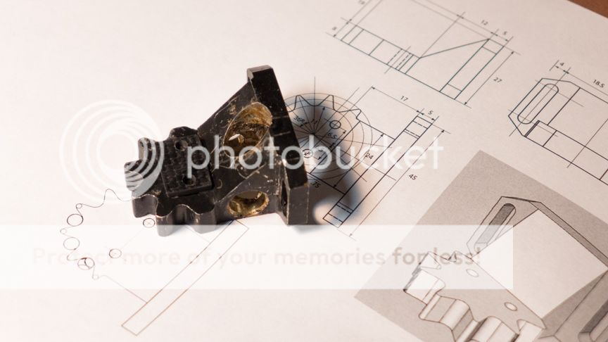
This is first version. I drilled holes from different sides. Then, I filled these holes with foam glue. But after listening, I realized it was a bit too much of damping although the head shell was very quiet. The sound was very natural with slight compressed sound stage. So, I took foam glue out of the head shell. It was an improvement with sound stage. But I was still not satisfied.

This is current version of the head shell. It is even 5 mm shorter than previous one. I did it from a solid block of 2024 aluminum. Its bass is further enhanced. Sound stage is excellent. However, background is not as dark as previous head shell. I am very happy with it. This is the version I will keep.
When I designed the head shell, I optimized it with the following measures.
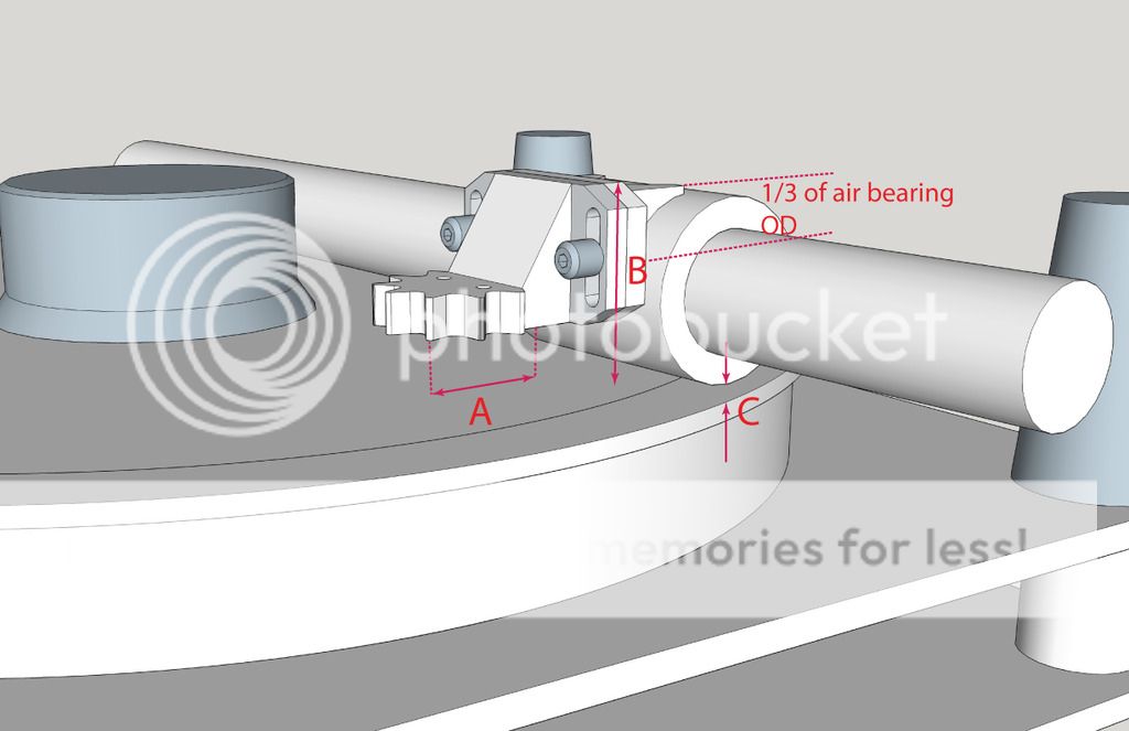
1, I added two slots on the sides of the head shell. These two slots enable me to adjust azimuth and rough VTA. The reason I need to adjust VTA on head shell is I can let the bearing closes to surface of record as close as I can. Please see the photo.

The gap between the bottom of air bearing and record surface is about 3 mm.
2, I made A distance as short as possible. As I said before, the new head shell is 5 mm shorter than previous one.
3, I made the distance C as short as possible. It is now about 3 mm.
4, I made the distance B as high as possible. The head shell attaches about top 1/3 area of air bearing.
For material, I have been using 2024 aerospace aluminum for head shell and magnesium for the part which attaches the head shell and air bearing. I think it is a good combination with right amount of damping. I tried brass. It is another good material to use for head shell. But brass is heavy.

I also redesigned counter weight part of arm. I used 2 mm carbon fiber sheet sandwiched with .5” balsa wood. The tail has 4 positions so I can move the counter weight to different position and change the weight distribution. What I learnt is the counter weight should be as close to the arm pivot as possible. Actually, it is very easy to understand that. Let’s assume you are holding a stick. The shorter the sticker is, the more control you have. Of course, when the counter weight is close to the center, it adds more mass to the arm carriage.
In the meantime, I newly acquired a Benz Micro LPs cartridge. The Benz is mainly for playing classical records.
For my another air bearing arm, I may redo the head shell as well. However, I am completely satisfied with that arm with modified Denon DL-103r for playing jazz records now.
I have been trying different structures and materials for the head shell.
For the structure, I did three versions of head shells.

This is first version. I drilled holes from different sides. Then, I filled these holes with foam glue. But after listening, I realized it was a bit too much of damping although the head shell was very quiet. The sound was very natural with slight compressed sound stage. So, I took foam glue out of the head shell. It was an improvement with sound stage. But I was still not satisfied.

This is current version of the head shell. It is even 5 mm shorter than previous one. I did it from a solid block of 2024 aluminum. Its bass is further enhanced. Sound stage is excellent. However, background is not as dark as previous head shell. I am very happy with it. This is the version I will keep.

When I designed the head shell, I optimized it with the following measures.
1, I added two slots on the sides of the head shell. These two slots enable me to adjust azimuth and rough VTA. The reason I need to adjust VTA on head shell is I can let the bearing closes to surface of record as close as I can. Please see the photo.

The gap between the bottom of air bearing and record surface is about 3 mm.
2, I made A distance as short as possible. As I said before, the new head shell is 5 mm shorter than previous one.
3, I made the distance C as short as possible. It is now about 3 mm.
4, I made the distance B as high as possible. The head shell attaches about top 1/3 area of air bearing.
For material, I have been using 2024 aerospace aluminum for head shell and magnesium for the part which attaches the head shell and air bearing. I think it is a good combination with right amount of damping. I tried brass. It is another good material to use for head shell. But brass is heavy.

I also redesigned counter weight part of arm. I used 2 mm carbon fiber sheet sandwiched with .5” balsa wood. The tail has 4 positions so I can move the counter weight to different position and change the weight distribution. What I learnt is the counter weight should be as close to the arm pivot as possible. Actually, it is very easy to understand that. Let’s assume you are holding a stick. The shorter the sticker is, the more control you have. Of course, when the counter weight is close to the center, it adds more mass to the arm carriage.
In the meantime, I newly acquired a Benz Micro LPs cartridge. The Benz is mainly for playing classical records.
For my another air bearing arm, I may redo the head shell as well. However, I am completely satisfied with that arm with modified Denon DL-103r for playing jazz records now.
Last edited:
I have been thinking about the advantages and disadvantages of an air bearing tonearm as mine. Frankly speaking, I fail to figure out any disadvantages of such arm except a noisy air compressor. If anyone can tell me the disadvantages of air bearing arm, I will be very happy to learn.
As I know, the biggest disadvantage people claim is the difference of vertical mass and horizontal mass of an air bearing arm. Here is what Michael Fremer in Kuzma Air Line Tonearm review claimed.
"In conventional pivoted arms the arm/cartridge system moves vertically and horizontally around a common point; thus, horizontal and vertical effective masses are very similar. In linear trackers there is a big difference between the effective vertical and horizontal masses. Being a pivoted system in the vertical axis, a linear tracker's effective vertical mass is low because it consists of the relatively short armtube and cartridge. Horizontal mass is much larger: it includes the entire arm/sleeve assembly as well as the cartridge, all of which must be carried across the record and which do not benefit from being a pivoted system.”
Even here, Fremer failed to point out why the difference between vertical mass and horizontal mass doesn't benefit linear arms including air bearing arms.
Although I am not sure why the difference in vertical and horizontal mass is a disadvantage, I would say the difference for a mechanical linear arm can be significant enough not to ignore it no matter its impact is positive or negative. But for an air bearing arm, such difference is almost neglectable. It means nothing to say that there is difference between horizontal mass and vertical mass without relating the mass to cartridge movements.
Let’s assume an air bearing arm’s vertical effective mass is 20 grams. Its horizontal effective mass is 10 times of its vertical mass, i.e. 200 grams.
Groove forces the arm moving horizontally and vertically. The cartridge sees two kinds of forces. One is horizontal force, which I call it Fh. Another force is vertical force, which is Fv.
Fh=μWh
Where μ is coefficient of friction. Wh is horizontal mass.
Fv=μWv
Where μ is coefficient of friction. Wv is vertical mass.
The coefficient for air bearing is almost equal to zero.
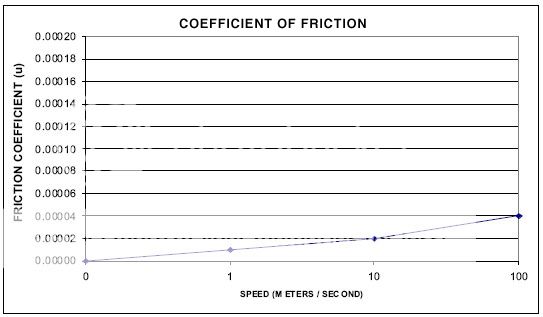
Air bearing arm moves so slow that it is very safe to assume its coefficient of friction is 0.000005.
So, the force required to move the arm horizontally is
Fh=200x0.000005=0.001 gram
The force required to move the arm vertically is
Fv=20x0.000005=0.0001 gram
The difference is 0.0009 gram.
Now, you can see because the difference of vertical and horizontal forces that a cartridge sees is so small. The difference of vertical and horizontal mass is completely insignificant. This also explains why air bearing arm puts minimum stress on cantilever. It also shows the superiority of an air bearing arm.
I have to admit that I don’t have engineering background. What I am doing is to try to remember what I learnt in high school.
Thanks for sharing. I had also asked a query about linear air bearing having mass and its effects. I think it was in another thread. What I wanted to know what forces move the linear tonearm and will it requires biasing. Now I know the force required to move an arm is very very low. I wonder if one can make very light tonearm and to damp the resonance a liquid filled one perhaps. ? A townshend type but liquid filled in cavities of hedshell or armtube ? i.e. not separate reservoir.
Regards.
Regards.
Thanks for sharing. I had also asked a query about linear air bearing having mass and its effects. I think it was in another thread. What I wanted to know what forces move the linear tonearm and will it requires biasing. Now I know the force required to move an arm is very very low. I wonder if one can make very light tonearm and to damp the resonance a liquid filled one perhaps. ? A townshend type but liquid filled in cavities of hedshell or armtube ? i.e. not separate reservoir.
Regards.
Hi Hiten,
In your post, there are two questions.
First, there is no skating force for linear tracking arms.
2nd, if I understand it correctly, you want to fill silicone fluid into the head shell or arm tube. To do so will make unnecessary complicated structure of head shell or arm tube. This kind of damping isn’t same as what I did for my air bearing arms. Yours is to damp the resonance of material. My damping devices have two kinds. One is to use silicone though. Another is to use Eddy Current device. Both are to reduce the inertia of arm carriage.
I have a new idea to implement Eddy current damping device and may work on it later on.
Jim
Last edited:
Thanks.
Reducing inertia of arm with eddy current sounds interesting. Also with regards to lateral and vertical mass. I had posted a tapering triangular tonearm design in some thread. It would be of equal mass on both plane I think. Not sure though. will post link soon.
Regards.
Reducing inertia of arm with eddy current sounds interesting. Also with regards to lateral and vertical mass. I had posted a tapering triangular tonearm design in some thread. It would be of equal mass on both plane I think. Not sure though. will post link soon.
Regards.
It was here
http://www.diyaudio.com/forums/analogue-source/13372-diy-schroeder-tonearm-106.html
but I must confess the vertical mass was not on my mind at that time. I was thinking about having rigid shape (Triangle) which would resist tortional effects for unipivots.
Regards.
http://www.diyaudio.com/forums/analogue-source/13372-diy-schroeder-tonearm-106.html
but I must confess the vertical mass was not on my mind at that time. I was thinking about having rigid shape (Triangle) which would resist tortional effects for unipivots.
Regards.
Hi Hiten,
I checked your link. The link is refer to pivot arm. For a pivot arm, its vertical and horizontal masses are similar. It is not a problem for pivot arms. As I said before, the difference of vertical and horizontal masses is not a problem for air bearing arm as mine due to low friction.
I don’t like to use three different materials to form an arm wand. It may damage the integrity of arm wand. I don’t see the need for three section arm wand because masses difference is not an issue for pivot arms.
Jim
"As I said before, the difference of vertical and horizontal masses is not a problem for air bearing arm as mine due to low friction."
Jim, since you're an expert on air bearings, have you ever thought of using air bearing for VERTICAL movement? Almost all tonearms' vertical movement is based on pivoting or a form of seesaw action, the shorter the arm the more sensitive to VTA. If we have an air bushing for the headshell to slide up and down without changing any angle, the VTA will be always constant, a pistonic movement. No more endless VTA adjustment and obsession! The headshell will be extremely short and low mass or almost headshell at all. The 'counterweight' can be attached to a string for adjusting VTF. I don't know if there's any bushing small and low mass enough for that function. And the air hose can be shared with the horizontal bearing which cannot have rotating movement, which might add to complexity. This is just a thought experiment and often wonder if we can dispense the seesaw type of bearing for vertical movement.
The only mention online is a drawing from Simply Physics' concept tonearm using magnetic slide, which is not practical and too close to the cartridge.
An externally hosted image should be here but it was not working when we last tested it.
Hi DD,
The arm you are describing is in effect linear tracking both vertically and laterally. Unfortunately making an arm as you suggest will actually have very little impact on VTA. The vast majority of VTA error is due to the slope of the record surface. Think of warps as hills and valleys. To get from the bottom of a valley to the top of a hill you have to go up a slope. This slope makes up most of the VTA error. The angle a vertically pivoted arm pivots by tends to be very small. It is true that a shorter arm will have greater VTA error than a longer one but the arm would have to be very short before the error due to the pivot was as significant as that due to the slope of the record surface. My calculations based on actual measurements of warps suggest that the arm would have to have an effective length of only 30mm before error due to pivot was as great.
Yes the proposed design would have slightly less error than a pivoted design and would be immune to differences in record thickness but the added complexity would almost certainly outweigh this.
Jim.
Love the look of your new carriage. I'll comment further in a separate post when I get a minute.
Niffy
"Yes the proposed design would have slightly less error than a pivoted design and would be immune to differences in record thickness but the added complexity would almost certainly outweigh this."
Thanks for the reply, Niffy. It wasn't just VTA I was concerning with but a way to reduce mass even further... to push it to the extreme. I also wonder if we can use roller, telfon slides, or linear bearings etc... instead of air bearing, like a mechanical linear arm. Even in a pivot arm, I want to see a split plane type a la Dynavector with a vertically straight bearing.
You're right, as always, that the added complexity is probably not worth pursuing. It's sure fun to think about! 😀
Hi DD,
Actually, I don’t change VTA too much once I set it correctly using USB microscope. I personally think it is not worth to do it. It makes the head shell too complicated. I have made many different versions of head shell and realized how important the head shell is. It is probably not a good idea to mess up the head shell. My philosophy for head shell is short, simple, solid, heavy and multi surfaced.
Jim
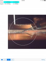
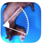
I sometimes use Mac App Photo Protractor to measure VTA. I would suggest to use it on iPad. Here is a screen shot of VTA of my cartridge.
Attachments
Last edited:
- Home
- Source & Line
- Analogue Source
- DIY Air Bearing Linear Arm