Thanks ZM for the kind reply, appreciated...
Care perhaps to elaborate a bit more in layman's terms on how it works... and if not abusing perhaps in what measures it limits current pulses (any rough calcuation?)
Many many thanks again
Claude
Care perhaps to elaborate a bit more in layman's terms on how it works... and if not abusing perhaps in what measures it limits current pulses (any rough calcuation?)
Many many thanks again
Claude
While at it, went the trouble of reading the article again and in more depth this time before asking silly questions and borring others 🙂
I don't know if this has been mentioned before, but my feeling is the graph page 15 labelled "THD SPECTRUM W/O JUMPERS" is correctly labelled... but the wrong graph (posted twice in fact as identical to the one above). My feeling is we should have there "THD SPECTRUM WITH JUMPERS" for 4R etc., of course with the appropriate graph. Not a criticism of course, just noting it "while at it" and because it is indeed of interest... and for sure will be for many as expecting many folks to get attracted by this amp and to read the article. My apologies to Papa and others if I should be wrong or this has been already addressed in this thread.
Many thanks again for your help
Claude
each resistor is as deliberately set water tap
resistor is limiting current in each moment, same as you adjusting water flow with tap
for better understanding - you need to read electronic basics , plenty of sources for that
many books about amplifiers are having first or even few chapters exactly about basics
do not skimp those chapters ...... I did, repeatedly ....... only to realize that I can understand squat about gain stage if I don't know what elementary parts are for
Attachments
Thanks again ZM for your kind reply
Yep, I understand the tab allright, in fact I was rather looking into time constants etc. , I am a bit rusted on that (it has been, err, decades since I graduated!!!)
Let's see if my understanding is correct, that is if you don't mind, sorry for wasting time on such trivial things...
Ignoring for now the rest of the circuit (the 221k deviation is a more shut down tab, and transistors are not getting work)... My understanding is that R4 C5 is in parrallel to C2 and hence to the voltage of the SMPS. Therefore C5 would load up slowed by a negative exponential with time divided by a time constant equal to R4 C5. So, at least I believe I understand the slow load up of C5 through R4... and the thumps reduction thanks to that time constant slowing things or keeping them alive longer when switching on and off respectively.
In fact what I don't get is the slow load up of C2, as that one seems quite huge with 15000uF... and there are 2 of them! They seem directly (well, small R = 0.33 inbetwen) exposed to the SMPS 24V without anything to slow inrush current, so the SMPS having a hard work. That is in fact what is confusing me.
I understand there are other big or bigger caps in the circuit but these aren't affecting the PS, so not my worries (the huge cap for the sound variation has been explained and the output DC decoupling cap is just big enough to enable bass frequencies with reasonably low impedance loudspeakers).
So, in short, is there here any clever thing enabling such a high value of C2 without the SMPS going in hiccup mode?
Many thanks again
Claude
Claude
I was speaking in general what resistor in series is doing
however - in this case 0R33 is value chosen for other purposes - strictly for filtration, not current limiting
what is main factor for slow ramp up, is internal current limiting of switching PSU used, nothing else
result is that voltage at PSU output is rising in steps, as long is needed to reach max voltage
say that you connect little amp to 24V Accu - there will be huge current surge during powering up, due to low internal impedance of Accus
Thanks ZM!
Soooo... my assumptions seem right, as said I discarted the small R that is there for pure RC low pass filtering purpose... and you do confirm that it is just the SMPS ability to cope with 30 000uF charging that enables starting-up.
Must say, it is pretty amazing for such a small SMPS, well done by Meanwell and well chosen by Papa. That SMPS is trully charging huge loads per batches without triggering the safety mode at start-up..
In that case the SMPS might or might not indeed be able to start up two ACA Minis with 60 000uF without a softstart inbetween... who knows LOL?
Thanks a lot ZM for your kind exchange
Claude
I have enough amps to play with and also to build, but I must confess that building 2 ACA Mini to play with, in various configurations with efficient speakers, is quite tempting...
Enjoy your Sunday eve all of you
Claude
Enjoy your Sunday eve all of you
Claude
Gentle reminder: I'll be choosing the recipients from among members who read post#1 of the thread below, and send me a PM containing their four answers, before Tuesday 21 Dec at 1:00AM, San Francisco time.
https://www.diyaudio.com/community/threads/free-pcb-clone-of-aca-mini-to-a-good-home.380272/
https://www.diyaudio.com/community/threads/free-pcb-clone-of-aca-mini-to-a-good-home.380272/
Being a headphone guy, I couldn't resist listening to the ACA Mini through headphones. I made a XLR 4-pin connection with open wires on the other end (since most of headphone cables are balanced), and hooked them into the speaker out of the AC Mini. My first impressions are "nice". Well rounded, full sound. I might even like it more than the WAMMY! Not as good as the Mainline 😉
There does seem to be some noise when RCA cables are plugged in, but silent with nothing plugged in. I have to explore. Maybe it's a grounding issue.
If I get my act together, I think I will build a little wood case with both speaker posts and a 1/4" switched jack.
There does seem to be some noise when RCA cables are plugged in, but silent with nothing plugged in. I have to explore. Maybe it's a grounding issue.
If I get my act together, I think I will build a little wood case with both speaker posts and a 1/4" switched jack.
Re Tower of power: It might be nice if there was an option to have the diystore board size increased to the same overall dimensions as the ACP+ with the same four mounting holes in the corners. You could then use commercial standoffs to mount one above the other, perhaps with an additional ground plane on the top as a dust cover.
Yessss, or better yet, shrink the ACP+ board. I’ve always thought that one could be a bit smaller.Re Tower of power: It might be nice if there was an option to have the diystore board size increased to the same overall dimensions as the ACP+ with the same four mounting holes in the corners. You could then use commercial standoffs to mount one above the other, perhaps with an additional ground plane on the top as a dust cover.
Obviously, this doesn’t really help those like me who’ve already built both the ACP+ and ACA mini in their current forms.
But I should have a solution to that in a week or two. 😉
Built mine today, fast and easy build, took just over an hour.
Still need to bias and try it out
Still need to bias and try it out
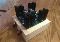
Thanks for Papa's generosity, I was able to build one yesterday.
I also made a small wood base and added some binding posts.
I look forward to playing around with the jumpers over the holidays.
This is going to be fun.
I also made a small wood base and added some binding posts.
I look forward to playing around with the jumpers over the holidays.
This is going to be fun.
Attachments


Nice! I like the binding posts you chose. Sleek and clean.Thanks for Papa's generosity, I was able to build one yesterday.
I also made a small wood base and added some binding posts.
I look forward to playing around with the jumpers over the holidays.
This is going to be fun.
So many great ideas floating around to admire and consider when I’m able to get a kit and start building. Good job fellas!
- Home
- Amplifiers
- Pass Labs
- DIY ACA mini