Question, sorry if this has been covered. My amp is up and running in its new enclosure. I know this is a very simple design, but is it normal for the amp to continue playing for a few if it is still getting signalafter shut off, to the point where it gets all garbled? Is it also normal for it to store energy onboard if it does not go through that garbled phase due to lack of signal? I ask because I have a preamp that make a slight noise when I run it on, and was suprised ot hear it turn on without the amp on after a few days of not playing. I think I read about this somewhere is in this thread, but cannot find it. Thank You.

Yes. The amplifier keeps playing for a little while as the power supply filter/reservoir capacitors discharge.
EDIT: Whoops… that’s not what happens in this amp, see Nelson’s reply’s below -
EDIT: Whoops… that’s not what happens in this amp, see Nelson’s reply’s below -
Last edited:
The switch just shuts down the bias. If you feed it enough input when it's off, some of it will bleed through.
No, the ps filter caps are kept charged. If you want to really turn it off
then pull the plug...
then pull the plug...
just finished building a kit. VB for left Channel wont get higher than 26mV. VO is 11.5V
Right channel is working ok.
What have a done wrong?

Right channel is working ok.
What have a done wrong?
resistors placement. diodes, soldering,no shorts......
it must be something
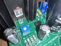
keep avalanche of pictures, we can't trust you on word
I mean - without pictures we can't even say what's most suspicious
if everything else is OK, I could say that most likely culprit is that you damaged one of trimpots while soldering
but, who knows .....
it must be something
keep avalanche of pictures, we can't trust you on word
I mean - without pictures we can't even say what's most suspicious
if everything else is OK, I could say that most likely culprit is that you damaged one of trimpots while soldering
but, who knows .....
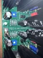
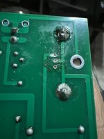
I’ve checked all resistors, capacitor orientations, resoldered all joints for left channel. No shorts that I can tell. The trim pots do alter the VO and VB voltage. It’s just that P1 trim pot only gives a VB range of 0mV to 27mV from counterclockwise to max clockwise. VO I can get it to be 11.5V as expected. While The right channel is biasing correct values. Is it still potentially a trim pot issue or the jfet/mosfet? (Sorry I’m not sure how it check this).
Attachments
-
 93FE9B87-1CFA-46D0-809D-70952BBB6725.jpeg441.9 KB · Views: 115
 -
 5000A9C9-30F5-4F56-A2F6-97C4C60EC51D.jpeg410.2 KB · Views: 111
 -
 65A4E8B8-1863-445B-9C59-9BD772AB0281.jpeg417.8 KB · Views: 115
 -
 C9A5BE24-1FA2-47AC-A778-0BDE8D349DDD.jpeg465.4 KB · Views: 115
 -
 5DECB8CF-CF66-4124-BFCB-2F34C460948C.jpeg433.7 KB · Views: 107
 -
 45EAE623-97F8-4B9D-B355-057F38868FF1.jpeg405.8 KB · Views: 114
power off, desolder both mosfets, remove them; easiest to do if you add solder to all 3 pads and heat them together with solder tip leaned to heat them at once
then clean pads with solder sucker
that to exclude potentially gate leak, to deduce is there a problem with JFet or mosfet
set both trimpots to min, measure VO and VB, write down
set both trimpots to max, measure VO and VB, write down
of course, there is the other way - replace JFets from one channel to other; if problem stays in same channel, JFets are OK, mosfet is Dodo
now, if counting on fact that you are able to ( same technique as for mosfets) cleanly swap JFets between channels - that is certainly best and fastest way of deducing a culprit
Thanks for your help ZenMod.
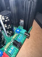
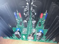
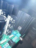
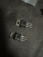
Ive managed to remove the IRF520. While the IRF9520, im really struggling to remove it. Ive put so much heat onto it now, if it wasn’t dead by heat originally, it probably is now. Sigh. Is there an easier way to remove the mosfets? It’s like the solder is also stuck on the other side of the pcb which is hard to access with the soldering iron.
Looks likely needing to get a replacement fet matched kit from the store at this stage. Assuming I can figure out how to remove these fets…
Attachments
What is your soldering gun set to? I have cooked a few mosfets in the past with the soldering gun and have not had one fail. They are surprisingly touch Did you add a big glob of solder to your gun tip?
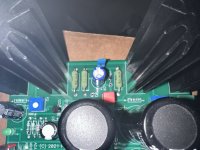
it’s on 430degrees c at the moment. Yep added a blob of solder on the tip. Ive got the solder mainly off the underside of the pcb. But it seems the fets legs got so much solder on it and it’s stuck on the top side of the pcb. Cant get the solder tip in the gap as there is one of the big caps in the way. That’s not easy to remove either.
Going to give up for now. Sorry, frustrated. Will try removing the big cap so got space to remove the solder from the fet legs tomorrow.
Going to give up for now. Sorry, frustrated. Will try removing the big cap so got space to remove the solder from the fet legs tomorrow.
- Home
- Amplifiers
- Pass Labs
- DIY ACA mini