
Perhaps the new SMPS that comes now with the kit has been lowered regarding its power delivery capability because most of it is mainly needed at start-up (hiccup mode etc.) to load the big caps, and not "once running". And I believe the newer kits come with a different resistor that slows the turn-on current rush, as discussed here rcently, so perhaps the new PS come together with the more recent "upgraded" kits... that are less demanding re power delivery at start-up. Hence the move from 90W to 48W.
Just my guess...
Claude
Just my guess...
Claude

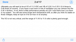
Voila. Haven't verified stocks or any parts changes. I made mine from page 4 of the manual in post #1
| PC BOARD | 1 | 2 CHANNEL PC BOARD | ||
| R1, R7 | 4 | 1K | DIGIKEY | PPC1.OOKYCT-ND |
| R2, R3 | 4 | 221K | DIGIKEY | PPC221KYCT-ND |
| RO, R4 | 3 | 6.8K | DIGIKEY | PPC6.81KYCT-ND |
| R5 | 2 | 475 | DIGIKEY | PPC475YCT-ND |
| R6 | 2 | 100 | DIGIKEY | PPC100YCT-ND |
| R8, R9 | 4 | 0.75 OHM 3W | DIGIKEY | PPC3W.75TB-ND |
| R10 | 2 | 0.33 OHM 3W | DIGIKEY | PPC3W .33CT-ND |
| R11 | 2 | 1.0 OHM 3W | DIGIKEY | PPC3W1.OTB-ND |
| P1, P2 | 4 | 1000 OHM PC MOUNT POT | DIGIKEY | 3386P-102LF-ND |
| 1 | 2 | LSK170 JFET | LS | |
| 2 | 2 | LSJ74 JFET | LS | |
| 3 | 2 | IRF9520 (HARRIS) | ||
| 4 | 2 | IRF520 (HARRIS) | ||
| C1 | 2 | 1 UF FILM CAP - WIMA | MOUSER | 505-MKS21/100/5 |
| C2, C3 | 4 | 15K UF ELECTROLYTIC | DIGIKEY | 495-77174-ND |
| C4, C5 | 3 | 1000 UF 25V ELECT | DIGIKEY | 493-5913-1-ND |
| C6 | 2 | 3.3F 2.7V SUPERCAP | MOUSER | 581-SCCR20B335PRBLE |
| INPUT CONN L | 1 | RCA INPUT PC MOUNT GRN | DIGIKEY | CP-1423-ND |
| INPUT CONN R | 1 | RCA INPUT PC MOUNT RED | DIGIKEY | CP-1419-ND |
| POWER CONN | 1 | PWR JACK 2.5X5.5MM | DIGIKEY | CP-037B-ND |
| OUTPUT CONN | 2 | TERM BLOCK 5MM 2 POS | DIGIKEY | ED-1609-ND |
| SWITCH | 1 | SPOT SWITCH | DIGIKEY | EG2355-ND |
| LED | 1 | LED | DIGIKEY | 1080-1063-ND |
| SCREW #3 M | 4 | M3X8 SOCKET HEAD | ||
| NUT #3 M | 4 | M3 KEPNUT | ||
| SCREW 6-32 | 4 | 6-32 x 0.25" | ||
| SPACER 6-32 | 4 | 6-32 x 0.5'' | ||
| HEAT SINK | 4 | AAVID T0-220 BOARD MNT | DIGIKEY | HS380-ND |
| POWER SUPP | 1 | MEANWELL GSM90B24-P1 M | DIGIKEY | |
| PS CORD | 1 |
Note that depending on what particular brand of output MOSFETs you use, that P1 & P2 may need to be substituted with 1.5K ohm or 2K ohm pots instead of 1K to reach the requisite recommended bias.
I know for the latest kits from the DIYAudioStore, the recommendation is to use 2K ohm pots. That’s what I have ordered for my build.
See post 1592.
Best,
Anand.
I know for the latest kits from the DIYAudioStore, the recommendation is to use 2K ohm pots. That’s what I have ordered for my build.
See post 1592.
Best,
Anand.
Ordered the BOM...
Substitutions... OK?
3F/2,7V Supercap - same size (3,3F)
1,5uF Wima - same raser size (1uF)
... and the world have ran out of 0,75 ohm resistors... :-/
(PPC1.00KYCT-ND + PPC3W1.OTB-ND has O insteps of 0 🙂 )
//
Substitutions... OK?
3F/2,7V Supercap - same size (3,3F)
1,5uF Wima - same raser size (1uF)
... and the world have ran out of 0,75 ohm resistors... :-/
(PPC1.00KYCT-ND + PPC3W1.OTB-ND has O insteps of 0 🙂 )
//
R10 is not needed in case you use a linear supply. And C3 is probably already covered with whatever final capacitor your linear power supply holds.If using LPS, R10 and C3 are not needed correct? Or they're not there for SMPS specifically?
@TNT: Consider increasing the value for R4 per Papa's post #1218 ( https://www.diyaudio.com/community/threads/diy-aca-mini.379037/page-61#post-7123575 )
Also, a number of other 0.33R, 0.75R, 1R, 3W metal film/metal oxide resistors are in stock at Digikey. (I don't know if this link will stay valid but you can try it: https://www.digikey.ca/en/products/...lrlD1JjehEbADZZXgATdmawcnJwgvNwlgBPJkbzGqQBoA)
Also, a number of other 0.33R, 0.75R, 1R, 3W metal film/metal oxide resistors are in stock at Digikey. (I don't know if this link will stay valid but you can try it: https://www.digikey.ca/en/products/...lrlD1JjehEbADZZXgATdmawcnJwgvNwlgBPJkbzGqQBoA)
When you are speaking from a Meanwell 24 spsu in front of this regulator board: that will not match, will not work!MW RS-50-24 + a regulator board.
This regulator board is designed for AC input, about 20 to 22VAC is OK for 24VDC output.
When you plan to connect the MW 24VDC after the rectifier diodes, the 24VDC input is to low for 24DC output!
I am using the same regulator board with a 20VAC/50VA toroid in front of it. Look here and scroll down some posts
Last edited:
BTW: you cannot call it "linear power supply" when you connect a linear regulator to a switching mode power supply!
Then I have a problem, as the AC line that powers my linear supply comes from a
solar array and batteries powering an inverter....
😉
solar array and batteries powering an inverter....
😉
I'm not calling it anything but a "regulator" - linear or not 🙂 - and I'm planning to connect to the input terminals of the regulator board - it actually works fine - I have done it for other builds - no problems...
Yes you lose 1 volt + need som regulation headroom so perhaps it needs 27V DC to produce 24 - and the MW is possible to adjust up to 27V so I think it will be fine. Also, I dont need "full" output power so I think I could spare a volt for Vcc if needed.
Thanks for your concern!
//
Yes you lose 1 volt + need som regulation headroom so perhaps it needs 27V DC to produce 24 - and the MW is possible to adjust up to 27V so I think it will be fine. Also, I dont need "full" output power so I think I could spare a volt for Vcc if needed.
Thanks for your concern!
//
Solbattinv hybrid? 🙄Then I have a problem, as the AC line that powers my linear supply comes from a
solar array and batteries powering an inverter....
😉
Sorry, it was not you speaking from a LPS...I'm not calling it anything but a "regulator" - linear or not 🙂
27 to 28V input should be OK, indeed!
I received the units this afternoon and I just hooked them up... but I only get 12V out out... hmmm...
Is there somewhere to program the board what to output except for the trimmer?
The MW does 28V at least it seems....
//
edit - yes there is strapping... 🙂
Is there somewhere to program the board what to output except for the trimmer?
The MW does 28V at least it seems....
//
edit - yes there is strapping... 🙂
Last edited:
- Home
- Amplifiers
- Pass Labs
- DIY ACA mini