Hi, sorry but I could not find 2 things in these 35 pages 🙂, please help my with:
- PSU 24V and what is the minimum amp requirement ? 5A like ACA V.18 ?
- can 2 Mini's be bridged and have 10W mono ? If so , what are the steps to do it ? Like ACA ACA V.18 ?
The BOM calls out a Meanwell supply of 24V at 3.75A. Bridging? Why not. But you'd have to invert the complimentary input on your own or hook up your own balanced connector as done with the ACA.Hi, sorry but I could not find 2 things in these 35 pages 🙂, please help my with:
Thank you.
- PSU 24V and what is the minimum amp requirement ? 5A like ACA V.18 ?
- can 2 Mini's be bridged and have 10W mono ? If so , what are the steps to do it ? Like ACA ACA V.18 ?
BTW the BOM is in this article:
https://www.diyaudio.com/community/attachments/aca-mini-article-pdf.995068/
and it has an error. 4 1000uF caps are needed, not 3.
OK. Thank you. Just lika an ACA then 🙂The BOM calls out a Meanwell supply of 24V at 3.75A. Bridging? Why not. But you'd have to invert the complimentary input on your own or hook up your own balanced connector as done with the ACA.
BTW the BOM is in this article:
https://www.diyaudio.com/community/attachments/aca-mini-article-pdf.995068/
and it has an error. 4 1000uF caps are needed, not 3.
Only if you use a balanced input.
If you want to drive it with a single-ended RCA input then you need a phase inverter. The trick that is used in the ACA works because the output is inverted.
If you want to drive it with a single-ended RCA input then you need a phase inverter. The trick that is used in the ACA works because the output is inverted.

So, I built my first amplifier! (only took 50 years)
First and foremost, kudos to Nelson for making this happen. I have been interested in the commercial FW amps for a long time using relatively efficient speakers for the last 10 years. I never really viewed them as a primary amp but always thought they would be fun to play with a secondary amp depending on the music and its demands. I have been to this site numerous times over the last 2 years as I did the Covid shuffle with audio equipment at home which ended up with me selling a full function tube preamp and 2 tube amps and replacing them with a XP22, XP25, and XA30.8. I had read as much as possible about the commercial products not really understanding the finer details discussed but still gleaned enough info to make the switch. I still had thoughts of eventually getting a FW amp also to play with. During a long running email with Kent English about all things Pass and his recommendations about what FW amp to try he mentioned doing one of the DIY versions or an ACA. So, back to this site and more reading. I figured I could probably pull off an ACA after some more research but wasn't sure something like a Aleph J, M2, or ZM SissySIT would be within my grasp. The one thing that slowed my down from jumping in was as straightforward as the ACA build appeared for a beginner the cost with the full chassis was a little more than I was willing to try. I just figured if I did the ACA and then moved on the FW clones the ACA would sit in the corner and collect dust.
Fast forward to this past Burning Amp and the ACA mini. In part of Nelson's presentation he mentioned that he hoped the mini version would encourage those who had been hesitant about trying an ACA to go ahead and jump. Well for me it was the final push in the right direction and I jumped in with both feet. When Kevin Heem offered the clone board GB I jumped at the opportunity. And as usual I have figured out, my enthusiasm was rewarded when Papa donated some Harris Mosfets.
So here it is, my ACA mini with Mark's SMPS.


Build was pretty straightforward with adequate reading and preparation. Had to do some minor parts substitutions as expected, missed the error on the BOM for 4 not 3 1000uF caps. No big issue, because you never just build one amp, I was already ordering parts for an Aleph J. I have 3 kids between 11-5 so my alone time for projects like this is after they are usually asleep. I stuffed everything but the Fets the first night, then finished with the Mosfet and Jfets the following night. Lessons were learned on how to bend leads and tape components so they do shift when you flip the board over to solder but all in all was pretty uneventful.
So the final moment came 2 nights later, as was quiet in the house and I decided to give it power. I hooked DMMs up to the source resistors to measure Vb on startup and flipped the switch........nothing! Checked the power supply, + blue light. Hooked DMM up to PS, we got voltage. Hooked back up to amp, still no green light or heat on the heatsinks. Well, turns out I put the power switch in backwards #@$%$##. After a quick session with the Solderpulit the power switch was correctly installed and voila, green light a heat on the sinks, and even better no smoke was released. I let it warm up and biased it up to around 0.3A that night. By now it spring break and Im off work with the kids. Hooked it back up and pushed bias up to 0.33A which seem to be the magic number with temps on heat sinks in the 57-58C range. So time to hear some music. Plan was to use some old NHT floorstanders that live in the garage but with kids home I was working off the kitchen table to stay around the family so I grabbed a left over NHT center channel to use. Hardly an ideal match, sealed four driver speaker with listed impedance of 6 ohm and "50-250W" power recommendations. But I went back and forth between channels using an iPhone as a source and not surprisingly I heard music! I let them play for about 4 hours the first day and no issues.
The next morning I moved the amp to my music room to burn in more. Unfortunately the mini split AC in there is dead so its dependant on house AC for cooling. Figured I would see how the bias and temps would behave in a slightly warmer room. It was around this time I heard a distant voice, a voice all the way from Asgard, it was Loki whispering "Release the smoke, release the smoke". Wrote off to being tired and chasing kids on spring break. Check back a little later after play with the kids outside in the warm So FL sun. Temps on the heatsinks where up to 62-63C so clearly bias needed to come down. I leaned over the amps to turn on the DMM i had hooked up and again heard Loki whisper "Release the smoke". Right about then i saw a drop a sweat fall off my forehead and hit the board, 2 seconds later the smoke was released and the bias on the Left channel quickly climbed. I flipped the power switch but the bias kept climbing so I quickly unplugged the power supply and the bias fell. I let everything cool off and check an hour later. Plugging the power supply back in quickly let the bias shot up in the Left channel only, power switch was still dead and not position killed power to the left channel.
So lesson learned, no So FL sweat on the amp boards. Clearly shorted something out. Only obvious damage is the source resistor for QL4 looks toasty. Haven't had a change to pull the heat sinks and take closer look, will hopefully do so tonight. Will likely need to pull the Mosfets and test them, suspect they fried. But this is part of the process, no I get to practice my problem solving skills. Will report back when I get the heat sinks off and can take better pictures.
On the bright side, after that I build a Quasimodo board without issue and successfully tested 4 transformers for future builds. The disease is real!
A big thanks to all involved here, I wouldn't have even considered this without everyone's support.

PS, in case anyone is wondering, inspiration for case design is from home, sweet home. Neyland Stadium, University of Tennessee

First and foremost, kudos to Nelson for making this happen. I have been interested in the commercial FW amps for a long time using relatively efficient speakers for the last 10 years. I never really viewed them as a primary amp but always thought they would be fun to play with a secondary amp depending on the music and its demands. I have been to this site numerous times over the last 2 years as I did the Covid shuffle with audio equipment at home which ended up with me selling a full function tube preamp and 2 tube amps and replacing them with a XP22, XP25, and XA30.8. I had read as much as possible about the commercial products not really understanding the finer details discussed but still gleaned enough info to make the switch. I still had thoughts of eventually getting a FW amp also to play with. During a long running email with Kent English about all things Pass and his recommendations about what FW amp to try he mentioned doing one of the DIY versions or an ACA. So, back to this site and more reading. I figured I could probably pull off an ACA after some more research but wasn't sure something like a Aleph J, M2, or ZM SissySIT would be within my grasp. The one thing that slowed my down from jumping in was as straightforward as the ACA build appeared for a beginner the cost with the full chassis was a little more than I was willing to try. I just figured if I did the ACA and then moved on the FW clones the ACA would sit in the corner and collect dust.
Fast forward to this past Burning Amp and the ACA mini. In part of Nelson's presentation he mentioned that he hoped the mini version would encourage those who had been hesitant about trying an ACA to go ahead and jump. Well for me it was the final push in the right direction and I jumped in with both feet. When Kevin Heem offered the clone board GB I jumped at the opportunity. And as usual I have figured out, my enthusiasm was rewarded when Papa donated some Harris Mosfets.
So here it is, my ACA mini with Mark's SMPS.
Build was pretty straightforward with adequate reading and preparation. Had to do some minor parts substitutions as expected, missed the error on the BOM for 4 not 3 1000uF caps. No big issue, because you never just build one amp, I was already ordering parts for an Aleph J. I have 3 kids between 11-5 so my alone time for projects like this is after they are usually asleep. I stuffed everything but the Fets the first night, then finished with the Mosfet and Jfets the following night. Lessons were learned on how to bend leads and tape components so they do shift when you flip the board over to solder but all in all was pretty uneventful.
So the final moment came 2 nights later, as was quiet in the house and I decided to give it power. I hooked DMMs up to the source resistors to measure Vb on startup and flipped the switch........nothing! Checked the power supply, + blue light. Hooked DMM up to PS, we got voltage. Hooked back up to amp, still no green light or heat on the heatsinks. Well, turns out I put the power switch in backwards #@$%$##. After a quick session with the Solderpulit the power switch was correctly installed and voila, green light a heat on the sinks, and even better no smoke was released. I let it warm up and biased it up to around 0.3A that night. By now it spring break and Im off work with the kids. Hooked it back up and pushed bias up to 0.33A which seem to be the magic number with temps on heat sinks in the 57-58C range. So time to hear some music. Plan was to use some old NHT floorstanders that live in the garage but with kids home I was working off the kitchen table to stay around the family so I grabbed a left over NHT center channel to use. Hardly an ideal match, sealed four driver speaker with listed impedance of 6 ohm and "50-250W" power recommendations. But I went back and forth between channels using an iPhone as a source and not surprisingly I heard music! I let them play for about 4 hours the first day and no issues.
The next morning I moved the amp to my music room to burn in more. Unfortunately the mini split AC in there is dead so its dependant on house AC for cooling. Figured I would see how the bias and temps would behave in a slightly warmer room. It was around this time I heard a distant voice, a voice all the way from Asgard, it was Loki whispering "Release the smoke, release the smoke". Wrote off to being tired and chasing kids on spring break. Check back a little later after play with the kids outside in the warm So FL sun. Temps on the heatsinks where up to 62-63C so clearly bias needed to come down. I leaned over the amps to turn on the DMM i had hooked up and again heard Loki whisper "Release the smoke". Right about then i saw a drop a sweat fall off my forehead and hit the board, 2 seconds later the smoke was released and the bias on the Left channel quickly climbed. I flipped the power switch but the bias kept climbing so I quickly unplugged the power supply and the bias fell. I let everything cool off and check an hour later. Plugging the power supply back in quickly let the bias shot up in the Left channel only, power switch was still dead and not position killed power to the left channel.
So lesson learned, no So FL sweat on the amp boards. Clearly shorted something out. Only obvious damage is the source resistor for QL4 looks toasty. Haven't had a change to pull the heat sinks and take closer look, will hopefully do so tonight. Will likely need to pull the Mosfets and test them, suspect they fried. But this is part of the process, no I get to practice my problem solving skills. Will report back when I get the heat sinks off and can take better pictures.
On the bright side, after that I build a Quasimodo board without issue and successfully tested 4 transformers for future builds. The disease is real!
A big thanks to all involved here, I wouldn't have even considered this without everyone's support.
PS, in case anyone is wondering, inspiration for case design is from home, sweet home. Neyland Stadium, University of Tennessee


Always been a Lego kid, fortunately my kids love them also. Golden chicken overseeing Mark’s filter was my 9yo daughter’s addition while we built the mini football field. Only difference is I’m old enough that when I wanted to make X-wings and TIE fighters all I had was a big bag of generic Legos unlike the intricate kits they make now.
So, 2 questions before I start debugging the smoked left channel:
1. Can you accurately measure/test the resistors in situ on the pcb? I know the Fets will need to be pulled for accurate testing.
2. Any good explanation why the bad left channel would still get power with the power switch off? Does the switch connect the DC power to the left and right channel separately?
The power switch does not disconnect the power, it simply shuts off the bias current.

So if one managed to short out the switch it could be in “off” position but still supply power to the bias circuit.
Don’t be the boy, don’t be the boy, Do’h Bart! (Matt).
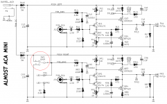
Rookie mistake 2, probably would have helped to download Marks schematic that the clone boards where based of not just Nelson original article. Especially since Mark’s is nicely labeled 🤦♂️
Rookie mistake 2, probably would have helped to download Marks schematic that the clone boards where based of not just Nelson original article. Especially since Mark’s is nicely labeled 🤦♂️
I am currently gathering the parts to complete my " Almost a clone" and have been having a difficult time finding the 3 watt resistors. They are either not in stock with a very long waiting time or require the purchase of a large quantity. I was wondering if it is possible to use 5 watt resistors or could that be a safety issue? Thanks
- Home
- Amplifiers
- Pass Labs
- DIY ACA mini