That's wonderful news Vincent. I'm really looking forward to seeing the F5m in the store.

How does it differ from the original?Plus a new F5 will be showing up in the store SOON!
Nelson will make his announcement when he's ready.
I have no intention of stealing his thunder. ⚡
I have no intention of stealing his thunder. ⚡
So... here it is. My Dual Mono ACA Mini Turbo.
If this thing turns out to do what I hope it will, I will supply pictures and other impressions when finished.
If it doesn't... this will be the last you'll ever hear of it.
Orders for boards and components will go out next week.
I plan on ordering 50 of each IRF, and hope this will be enough to find a couple of triplets.
I haven't put this in a seperate thread, as it's basically still an ACA Mini, just with a little nuts-ness on top.
Attachments
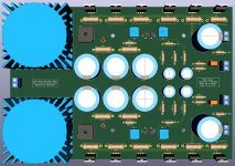
I assume the green traces on the left are for the mains in. If you separate the mains connections into two connectors, one for each transformer, then the boards could be cut in half for a more flexible solution in regards to heatsink placement. You can even have a breakaway down the center like how the DIYaudio power supply board has.
What chassis did you design this for?
Looks like fun!
What chassis did you design this for?
Looks like fun!
In the spirit of trying ideas, I moved the fets from my mini to a much larger heatsink and cranked the bias (slowly) to a little over 1.2 A.
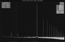
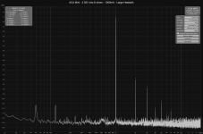
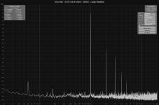
I have a rudimentary THD measurement setup using REW (thanks to xrk971) and while I don't trust the absolute values, I do think it is directionally correct. As expected, more bias gives lower distortion at the same power. In theory you get more headroom too, though I haven't tested that yet. Some graphs attached below at 1 watt and 4 watts. Jumper was in for all the tests.
@baeijsman do you plan to run 24V, or are you bumping that up too?
Attachments
-
 THD ACA Mini 4W 1260mA big sink.png73 KB · Views: 189
 -
 THD ACA Mini 4W 440mA.png75.1 KB · Views: 160
 -
 THD ACA Mini 1W 1260mA big sink.png78 KB · Views: 150
 -
 THD ACA Mini 1W 890mA big sink.png75.2 KB · Views: 150
 -
 THD ACA Mini 1W 420mA big sink.png77 KB · Views: 176
 -
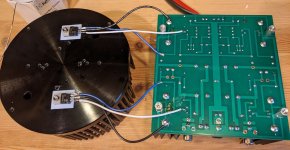 fet relocation bottom.JPG220.9 KB · Views: 185
 -
 fet relocation top.JPG238.7 KB · Views: 191
@Mikerodrig27: Definately possible, but it's made to fit precisely in a chassis i have found on eBay.
@N Brock: It will run on 24 volts like the original. I like the limited power-consumption.
@N Brock: It will run on 24 volts like the original. I like the limited power-consumption.
Attachments

@baeijsman
Nice work 👍
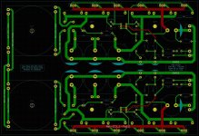
Seems that your primary (mains) is only for 230V since both the primary windings of each transformer are wired in series. Are you planning to modify it to have an international PCB, either 115Vac or 230Vac configurable by the user.
Can I please have the model number of your transformer ?
Thanks
Eric
Nice work 👍
Seems that your primary (mains) is only for 230V since both the primary windings of each transformer are wired in series. Are you planning to modify it to have an international PCB, either 115Vac or 230Vac configurable by the user.
Can I please have the model number of your transformer ?
Thanks
Eric
I assume the Talema is good for the current requirements? You know far more than I so I'm sure you've specified it wisely!
Aren't the ACA Mini's limited on the output to about 5 watts due to the rail voltage?
You should be able to use a transformer with two secondaries. One per channel. So the transformer could be a standard toroidal mounted to the chassis and the rest of the power supply bits on the board. This would allow a little more flexibility in trying different voltages. for instance, If you wanted your single rails to be 28v-30v to accommodate the extra mosfets, bias etc versus the 24v. And it would be dual mono but with one transformer.
https://www.antekinc.com/as-1222-100va-22v-transformer/
The transformer is a Telema 70061K.
It's 25VA, and since that equals the total comsumption of the original Mini, 2 should do the trick.
I might make modifications to the layout later, should there be any interest, but it won't happen until I'm sure it sounds any good and doesn't explode in my face.
@Mikerodrig: You are absolutely right, but I'm actually doing it this way, because I wan't it to be/sound as close to the original as possible AND not to use any more power.
The only thing I'm trying to achieive, is a slightly increased damping factor.
Sounds like a good plan. Should be fun to see how it all pans out! 🙂


Guys sorry if I have not read the past thread for my question. How can I eliminate the distortion Heared on the speaker after power on. Is there a circuit/kit out to address this or just allow the amp to warm up?
Can you post clear photos of your board? what are the voltages on each channel for VO and VB? VO should be 11.4-11.6 V and VB ~ 0.3-0.35 V.
@ronnieponsones : What distortion did you hear? Was the source already playing and you turn on the ACA mini and got distorted output? Or did you get a noise at power up even if the source isn't playing? Can you please describe what happened?
Source is already playing when I turn on the amp. I do know I need to warm up the amp first and play the source.
Mine does not have any distortion. None when first starting and playing music immediately.
- Can you post clear photos of your board?
- What are the voltages on each channel for VO and VB? VO should be 11.4-11.6 V and VB ~ 0.3-0.35 V.
- Home
- Amplifiers
- Pass Labs
- DIY ACA mini