@cubicincher
You state:
What resistance did you use? 0.75 ohms as spec’d in the original design? If so, you can go close to 0.4V (which is nearly 0.5A dissipation) since you have the Mosfets attached to much larger heatsinks.
The max dissipation of these IRF520/9520 is 40 watts. Nelson designed it to sing at nearly 5 watts dissipation which is comfortably below max.
Asking the collective group: How hard can we run these Mosfets for longevity sake? 1/3rd max dissipation, i.e. 10+ watts given enough heatsink?
Of course at that point, one would ask…just build a bigger amp!
Best,
Anand.
You state:
I biased the amp higher. At the moment 0.200 V (VB).
What resistance did you use? 0.75 ohms as spec’d in the original design? If so, you can go close to 0.4V (which is nearly 0.5A dissipation) since you have the Mosfets attached to much larger heatsinks.
The max dissipation of these IRF520/9520 is 40 watts. Nelson designed it to sing at nearly 5 watts dissipation which is comfortably below max.
Asking the collective group: How hard can we run these Mosfets for longevity sake? 1/3rd max dissipation, i.e. 10+ watts given enough heatsink?
Of course at that point, one would ask…just build a bigger amp!
Best,
Anand.
Anand, I'd start with a target junction temperature like 125C. Then I'd include conservative worst-case overestimates of all the thermal coefficients in the heat path.
Put these numbers into the appropriate thermal equations, both Cordell's book and Self's book go over the math pretty thoroughly, and calculate a final junction temperature. If it's below the target (125C), increase your-optimistic-guess of the transistor dissipation. On the other hand, if the calculated junction temperature is above the target (125C), decrease your-optimistic-guess of the transistor dissipation. After a few iterations, you'll converge upon The Final Answer. Now you know exactly how much transistor power dissipation is tolerable, under the worst-case conditions you've assumed. Done. Victory!
- Worst possible case, maximum ambient air temperature while amp is on. 54C / 129F ??
- Worst case max thermal resistance, heatsink bolt-hole to ambient air
- Worst case max thermal resistance, Keratherm pad / SilPad / Mica+Goop
- Worst case max thermal resistance, transistor package's junction-to-case "Theta JC"
- Your-optimistic-guess of the max power dissipated by the transistor, in watts.

Got it.
I’ll start with this equation:
Tj = Ta + (P * (Rjc + Rcs + Rsa))
Where:
Best,
Anand.
I’ll start with this equation:
Tj = Ta + (P * (Rjc + Rcs + Rsa))
Where:
- Tj = junction temperature
- Ta = ambient temperature
- P = power to be dissipated
- Rjc = thermal resistance of junction to device case
- Rcs = thermal resistance of device case to heatsink
- Rsa = thermal resistance of heatsink to ambient
Best,
Anand.
I think somewhere on the diyAudio Store site, or else on the ModuShop site, there's a thermal analysis of the ModuShop 4U 300 heatsink which separately covers (a) when there's exactly one power transistor mounted to the heatsink; (b) when there's exactly two power transistors mounted to the heatsink; and I think, (c) when there's four power transistors mounted to the heatsink. Spend a few minutes poking around, you might discover gold.
MJ,
Thanks for that. First I’m going to do the analysis with the specified heatsinks Nelson used in the ACA mini. That would give me a baseline, then I’ll start with the experimental heatsink, i.e. the 4U/300 but with 4 transistors mounted assuming one stereo ACA mini channel per 4U/300 heatsink.
Best,
Anand.
Tj = Ta + (P * (Rjc + Rcs + Rsa))
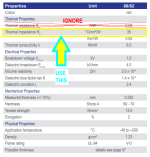
Rjc of IRF520 is 2.5 degC/watt
Rcs of Keratherm from DIYAudioStore is ~ 0.1 degC/watt
Rsa of Aavid heatsink specified is about 2.6 degC/watt
Power to be dissipated by the single device is 5 watts
Ta is about 55deg C (let’s pretend the heatsink is inside a sealed box).
Solving for Tj gives us: 81 degrees C << 125 degrees C.
With a larger heatsink, clearly there is more room to play with but I figure y’all would still recommend staying at under 100 degC for Tj for maximum longevity.
Best,
Anand.
Oops, I fear you have used the wrong line item from Kerafol/Keratherm's datasheet and so you got an incorrect numerical value of "Rcs".
You want the thermal impedance of a piece of Keratherm 86/82, squeezed in between a TO-220 (IRF520) metal mounting tab, and a semi infinite slab of solid aluminum. Take out your calipers and double check me; I claim the TO-220 mounting tab is 12mm X 9mm, so its area is 108 mm^2. Plugging that into Keratherm's equation
(degrees C) / (Watts) = 35 / (Area in mm^2) = 35 / 108 = 0.32 degreesC per watt
The nice thing is, the bigger the package, the greater its metal mounting tab area, so the heat flows through a greater area of Keratherm pad, and its thermal impedance falls. Therefore the big bohunker TO-264 transfers heat through Keratherm a lot better than TO-220. Which agrees with our intuition.
_
You want the thermal impedance of a piece of Keratherm 86/82, squeezed in between a TO-220 (IRF520) metal mounting tab, and a semi infinite slab of solid aluminum. Take out your calipers and double check me; I claim the TO-220 mounting tab is 12mm X 9mm, so its area is 108 mm^2. Plugging that into Keratherm's equation
- (deltaT in degreesC) * (Area in mm^2) / (Power dissipated in watts) = 35
(degrees C) / (Watts) = 35 / (Area in mm^2) = 35 / 108 = 0.32 degreesC per watt
The nice thing is, the bigger the package, the greater its metal mounting tab area, so the heat flows through a greater area of Keratherm pad, and its thermal impedance falls. Therefore the big bohunker TO-264 transfers heat through Keratherm a lot better than TO-220. Which agrees with our intuition.
_
Attachments
Modushop's website has a couple broken links, and their employees are on August holiday, so I used the internet wayback machine to discover what the links showed, a few months ago (when the links still worked). There's a screen capture below. If it's helpful, great. If not all that helpful, at least it demonstrates that you can sometimes use the wayback machine to discover what ought to be at the far end of a currently-dead link.
_
_
Attachments

MJ,
Thanks for checking my oversight. So with a TO-220 device, the Rcs is about 0.32 deg C/watt after calculating the thermal impedance of sandwiched Keratherm sized for a TO-220 area (it is nice to know that devices with larger surface areas calculate to smaller Rcs values!).
This changes numbers slightly but accuracy is still important. Still Tj will be comfortably under max of 125 deg C.
And Rsa for the 4U/300 heatsink appears to be anywhere from 0.31- to 0.36 degC/watt compared to Aavid’s 2.6 degC/watt.
All in all, we have room to play with regards to the dissipation of this TO-220 transistor. And at the end of the day, the elephants in the room are the thermal resistance of the heatsink to ambient, the amount of power dissipated by said device and additionally the local ambient temperature immediately surrounding the device itself.
Best,
Anand.
Last edited:
I recommend you spend effort and money to achieve supremely excellent thermal contact between the (relatively small) TO-220 mounting tab and the pad+heatsink. You want them perfectly co-planar and you want uniform pressure all across the tab. This may mean you apply clamping force to the transistor plastic body rather than torque-ing a mounting screw. Perhaps with a metal pressure-bar that forms the movable jaw of a vise; the vise's other jaw is the fixed heatsink.
_
_
Attachments
Hello Anand,
hello Mark Johnson,
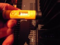
I have measured the temperature of the Mosfet from outside the heatsink (inbetween the fins, where the Mosfet is mounted inside).
I did this after one hour of listening. Temperature was 27° - 28° Celsius.
Roomtemperature during measurement: 20.4° C
Case is a Modushop Mini Dissipante 2U 250mm with 10mm front. Heatsink temperature coefficient 0.47° C / W.
https://modushop.biz/site/index.php?route=product/product&path=284&product_id=733
Bias resistors R8/R9 slightly lower than original: 0.68 Ohm / 5 W
VB still at 0.200 V.
Perhaps it helps?
Cheers
Dirk 😉
hello Mark Johnson,
I have measured the temperature of the Mosfet from outside the heatsink (inbetween the fins, where the Mosfet is mounted inside).
I did this after one hour of listening. Temperature was 27° - 28° Celsius.
Roomtemperature during measurement: 20.4° C
Case is a Modushop Mini Dissipante 2U 250mm with 10mm front. Heatsink temperature coefficient 0.47° C / W.
https://modushop.biz/site/index.php?route=product/product&path=284&product_id=733
Bias resistors R8/R9 slightly lower than original: 0.68 Ohm / 5 W
VB still at 0.200 V.
Perhaps it helps?
Cheers
Dirk 😉
Attachments
@cubicincher
So you have the bias at (0.2/0.68) or 0.3A. You can turn the pot a little more if you like. 0.25V will get you to 0.36A. But I’m sure you are happy with the sound where it is! Enjoy!
MJ,
I am considering using one of those Aavid mounting clips.

Best,
Anand.
So you have the bias at (0.2/0.68) or 0.3A. You can turn the pot a little more if you like. 0.25V will get you to 0.36A. But I’m sure you are happy with the sound where it is! Enjoy!
MJ,
I am considering using one of those Aavid mounting clips.
Best,
Anand.
Last edited:
Or get a piece of aluminum, drill two holes in it and drill and tap two holes in the heatsink.
I was just thing if you had a small piece of aluminum or even steel lying around, it would be quick and easy.
Great idea! I will upgrade to those spring steel mounting clips in my ACA mini amps.
I always worry slightly, slightly that the high heat cyklings of the class A amps will loosen the screws and/or the pressure on the active devices.
Will also upgrade my ACAs, Aleph Js and upcoming F5s with these spring steel fasteners for maximum peace of mind.
🙂🤚
https://www.digikey.se/en/products/detail/aavid-thermal-division-of-boyd-corporation/MAX08NG/1625322
- Home
- Amplifiers
- Pass Labs
- DIY ACA mini