Remember the target indicator of the 330-334 family is an analog meter with a 20 dB max dynamic range. Tying it to an FFT with 100+ dB range will highlight the 80 db below the normal minimum it was designed for.
1 mV full scale will probably not work out well as a minimum sensitivity.
The gain structure of the 334 is not ideal for what I'm trying to do here.
Hi Milos
The amplifier GAIN should not exceed about 30dB. This would mean that the 316 mv max signal would get to about 10 volts RMS or about 14.1 Vpp. You would need ± 18VDC on the opamps. I would choose to have the gain set for about 26dB, as I don’t want the opamp to get close to the rails. A number of opamps are good to about 4 volts from the rails before the distortion products raise their heads.
I hope this will help you make a good decision about you project.
Duke🙂
I'm getting a bit confused here about the scaling. My understanding is at the input to the meter amp is 1mVrms full scale. If this is so and this is the take off point then how will 30dB of gain give 10Vrms? 1mVrms is -60dBV.
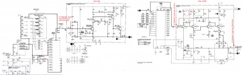
As I understand it ,here's the schematic of the A2 board with he voltages. I have to deal with 1mV.
Attachments
Last edited:
Thanks. The funny thing is that one of the best is that little Breeze Audio USB DAC.
On 12V, as you recommended it, the 5V reg. closest to the power input was cooking, so I bend it towards the back cover, dremmeled out a piece of ridge in the top cover where the regulator is, put a little heat compound on the place and now it's heat sinked nicely. That DAC is clean as a whistle.
On 12V, as you recommended it, the 5V reg. closest to the power input was cooking, so I bend it towards the back cover, dremmeled out a piece of ridge in the top cover where the regulator is, put a little heat compound on the place and now it's heat sinked nicely. That DAC is clean as a whistle.

The Breeze is AK4490 + XMOS + socketed dual opamp. I need to add that heat sink. the power supply seems not fully thought through. less than 12V it clips at 0dBFS more than 12V it cooks.
I have a similar china box with AK4497 X2 that I hope to get running soon. Its lots more flexible so I need to sort out what they got right and what isn't. It will be interesting and has potential for even better analog performance. But it may have really bad firmware.
I have a similar china box with AK4497 X2 that I hope to get running soon. Its lots more flexible so I need to sort out what they got right and what isn't. It will be interesting and has potential for even better analog performance. But it may have really bad firmware.
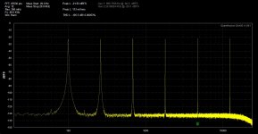
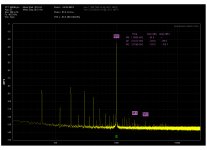
HP-334a A2 Imp Conv - Meter Amp
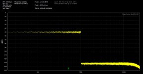
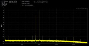
I made the changes, I wasn't expecting that big of a change.
Shocking really, the H2 and H3 down 100dB. So instead to make a buffer amp for the output, maybe I should make a new RMS meter amp. 😕
Pics, from the left: before, after mod
I made the changes, I wasn't expecting that big of a change.
Shocking really, the H2 and H3 down 100dB. So instead to make a buffer amp for the output, maybe I should make a new RMS meter amp. 😕
Pics, from the left: before, after mod
Attachments

Following along, but not sure what changes you made. Can you clarify.
Thanks
On the A2 board (Schematic in reply #505) , disconnected the meter by lifting D6 and bypassing D7.
Yes. those diode are the problem I also found. A new meter circuit/buffer to the meter is needed.
Now you can work down the distortion also in the Z converter.
THx-RNMarsh
Now you can work down the distortion also in the Z converter.
THx-RNMarsh
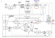
Block diagram
Looking of the block diagram and following the signal route ,it's look like the Meter Amp doesn't have any effect on the distortion performance of the 334a.
The Meter Amp only supply the output connector and bridge nulling circuit which is at the interaction points (Lamps) are DC. Richard Moore mentioned in his greening article that, when he disconnected the lamps ,or lamp, the distortion dropped. I would suspect that's only possible if the LDR's are nonlinear.
Attachments
Yes LDR are non linear.
Replace the lamps circuit with a resistor to check for loading effects.
Replace the lamps circuit with a resistor to check for loading effects.
Last edited:
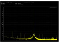
I did that before, but I don't think the THD is low enough to be a front end for the QA400.
that looks to be about as good as QA. same approx. What can be done to make it lower??
One reason I tried the 334a was its tunable notch. That part alone has good use with reducing fundemental for FFT processing.
THx-RNMarsh
- Status
- Not open for further replies.
- Home
- Design & Build
- Equipment & Tools
- distortion analyzer recomendations?