I tried improving the existing amp is several ways... increasing OLG for more fb and distortion reduction, parts changes etc. Nothing helped. I was left with the thought that the rectifiers off the output to the meter was a problem and could use a buffer between circuit and rect/meter. It was more work than i wanted to do.
THx-RNMarsh
THx-RNMarsh
Hi Miklos
1. What is the signal level @ the input of the meter range switch?
2. If the level is below or about 12 volts pp then add a unity gain buffer with a 50 ohm build out to J2
3. If >12vpp add an attenuator
4. The Opamp should be Unity gain stable and 500kHz BW, add ps decoupling and keep the voltage below its rating.
5. The LME49710 may be a good amp for this.
I look forward to your comments.
Duke🙂
The output Miklos is grabbing on C14 of the impedance converter is in between the two part attenuator. I'm wondering if he could grab it on C15 of the A2 board after the second part of the attenuator...then try 1 Audio1Man says with a op amp buffer.
Miklos, sorry I missed the first image you posted of Victor's oscillator straight into your QA.
Keep us posted.
Miklos, sorry I missed the first image you posted of Victor's oscillator straight into your QA.
Keep us posted.
Hi miklos,
Can you pick off the signal before the meter amp and use that? This circuit was conceived to drive the meter, and not much thought would have gone into having a spectrum analyzer hanging on that output. I suspect that HP's spectrum and network analyzers would be used directly as they have far greater performance than the 334A
I have one as well that I'll be diving into some day. I'm not above replacing some circuitry as long as I can keep the high bandwidth the 334A is capable of.
-Chris
I was thinking to do just that, and use an OPAMP for the output. I believe the Meter amp is in the circuit for the distortion analyzer to, not just for the meter.
I tried improving the existing amp is several ways... increasing OLG for more fb and distortion reduction, parts changes etc. Nothing helped. I was left with the thought that the rectifiers off the output to the meter was a problem and could use a buffer between circuit and rect/meter. It was more work than i wanted to do.
THx-RNMarsh
Yes, I know ,I read your letters. 🙁
The output Miklos is grabbing on C14 of the impedance converter is in between the two part attenuator. I'm wondering if he could grab it on C15 of the A2 board after the second part of the attenuator...then try 1 Audio1Man says with a op amp buffer.
Miklos, sorry I missed the first image you posted of Victor's oscillator straight into your QA.
Keep us posted.
Thanks, I was planing to go for that C15 to.
Hi Miklos
1. What is the signal level @ the input of the meter range switch?
2. If the level is below or about 12 volts pp then add a unity gain buffer with a 50 ohm build out to J2
3. If >12vpp add an attenuator
4. The Opamp should be Unity gain stable and 500kHz BW, add ps decoupling and keep the voltage below its rating.
5. The LME49710 may be a good amp for this.
I look forward to your comments.
Duke🙂
Hi Duke,
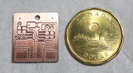
I will make the measurements. I was thinking for now to keep the impedance converter, add a 40dB buffer after the C15. Made a small SM board, maybe it would fit under the A2 PCB. The space there is ca. 4mm.
Miklos
Attachments
Hi,
Here's the result of the measurements.
The range sw. first section (front of the Impedace converter) only have two settings, 0dB and -60dB. Going to -60dB after the 7th step.
From 0.0003 to 0.3V it's 0dB and for 1 to 300V is -60dB the attenuation.
The range sw. second section, which is sitting in between the output of the Impedance Converter's C14 and the input of the Meter amp's C15 has seven steps from 0.0003 to 0.3V and after that from 1 to 300V resets to the 0.001V step and going through the steps again to reach 0.3/300V point. So the Impedance converter input never sees more than 0.3V (0.316) and at the input of the Meter amp the max voltage at full deflection is 1mV ,and the output is 100mV.
As I was going trough the above also realized that 100mV is not enough for the QA400 and I will need 60dB gain in the Opamp board to reach 1V out to use the full ability of the QA400. Am I right in this?
Hi Miklos
Get a cup of coffee. 20dB gain (10x) will make 100mv goto 1Volt, 60dB (1000x) gain would make 100mv goto 100 Volts.
Duke🙂
Get a cup of coffee. 20dB gain (10x) will make 100mv goto 1Volt, 60dB (1000x) gain would make 100mv goto 100 Volts.
Duke🙂
Hi Miklos
Get a cup of coffee. 20dB gain (10x) will make 100mv goto 1Volt, 60dB (1000x) gain would make 100mv goto 100 Volts.
Duke🙂
Hi Duke,
You are sort of right, but the level at the Meter amp input is only 1mV, and if I want to use the opamp circuit instead of the distorting Meter amp for the output, I have to use the Meter amp input for the source.
Miklos
If you have to amplify 60dB you will have to do it in several stages to maintain the bandwidth.
At this point I would calculate or even better measure the noise at the output of the stepped attenuator.
You could end up with the same as what you have now.
At this point I would calculate or even better measure the noise at the output of the stepped attenuator.
You could end up with the same as what you have now.
Last edited:
If you have to amplify 60dB you will have to do it in several stages to maintain the bandwidth.
At this point I would calculate or even better measure the noise at the output of the stepped attenuator.
You could end up with the same as what you have now.
Hi,
I don't have a clue how to measure noise on a 1mV signal, I guess my QA400 wouldn't tell me enough. Maybe the 600kHz bandwidth is not needed , do you think two stages would be enough for ca. 100kHz bandwidth?
Hi Miklos,
100 KHz is barely enough. Normally you want at least 10X the highest frequency you are going to measure. With the extra bandwidth, this THD meter will let you know if something is oscillating ultrasonically.
So, if you must, 100 KHz is enough. Many products on the market for audio have ceilings of 100 KHz. If by chance you can extend that, do so.
-Chris
When it's comes signal levels that low one should preferably do it in a Faraday cage, with no switching power supplies in sight etc. If I want to measure inside of the 334a, the cover have to be off, and that changes everything, except maybe the distortion.
Hi Miklos,
100 KHz is barely enough. Normally you want at least 10X the highest frequency you are going to measure. With the extra bandwidth, this THD meter will let you know if something is oscillating ultrasonically.
So, if you must, 100 KHz is enough. Many products on the market for audio have ceilings of 100 KHz. If by chance you can extend that, do so.
-Chris
Hi Chris,
I would go for the lower bandwidth because the simpler amp it would need for the +60dB gain ,and leave the oscillation detection to the scope.
Hi,
I don't have a clue how to measure noise on a 1mV signal, I guess my QA400 wouldn't tell me enough. Maybe the 600kHz bandwidth is not needed , do you think two stages would be enough for ca. 100kHz bandwidth?
It depends on the op amps use. That what the GBP figure of merit is on the data sheet is for.
Divide this figure by the gain of the amplifier and it give a estimate of bandwidth. It's just an estimate because not all specimens of the op amp will be the same. Even if the data sheet claims they are.
As Chris pointed out try to keep the bandwidth of the 334A.
You might need three 20dB stages to obtain this. Equalization may be necessary to keep the band pass flat. There is a lot of this in the existing meter amp.
The Shibasoku 725D has a 1 db rise above 100kHz all the say out to 500kHz. This is acceptably because that's what the 725 is spec'd for. Accurate to one decibel.
Remember the target indicator of the 330-334 family is an analog meter with a 20 dB max dynamic range. Tying it to an FFT with 100+ dB range will highlight the 80 db below the normal minimum it was designed for.
1 mV full scale will probably not work out well as a minimum sensitivity.
1 mV full scale will probably not work out well as a minimum sensitivity.
It depends on the op amps use. That what the GBP figure of merit is on the data sheet is for.
Divide this figure by the gain of the amplifier and it give a estimate of bandwidth. It's just an estimate because not all specimens of the op amp will be the same. Even if the data sheet claims they are.
As Chris pointed out try to keep the bandwidth of the 334A.
You might need three 20dB stages to obtain this. Equalization may be necessary to keep the band pass flat. There is a lot of this in the existing meter amp.
The Shibasoku 725D has a 1 db rise above 100kHz all the say out to 500kHz. This is acceptably because that's what the 725 is spec'd for. Accurate to one decibel.
Hi David,
Thanks for the advise. I will try to make a two stages amp, since I have the board for it. If it turns out promising, I will make a tree stages one.
- Status
- Not open for further replies.
- Home
- Design & Build
- Equipment & Tools
- distortion analyzer recomendations?